Last Updated on 14 February 2024 by Suffocation
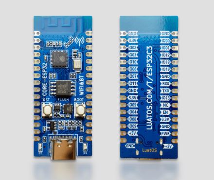
Ich war mal wieder zu Besuch beim schnellen Ali und stöberte einwenig herum als mir dieses Board auffiel. Es besitzt einen ESP32-C3 und ist in einem Formfaktor der auf ein Breadboard passt.
What is a preview: Da ich immer mehr den Überblick über die bestellte Hardware verliere, werde ich nach der Bestellung eine kleine Vorschau schreiben. Wenn ich dann zu der Hardware komme werde ich das ensprechende Preview durch den eigentlichen Beitrag ersetzen. Somit erhaltet ihr die Möglichkeit schon mal die bald Kommende Hardware zu besichtigen und zu kommentieren. Die Beiträge werde ich dann nach euren Kommentaren oder nach meiner Laune und Zeit priorisieren ;).
View
Description
Nettes kleines Board, mit einem ESP32-C3 hier ein paar zusätzliche Daten:
- Dimensions 21mm wide * 51mm long
- 1 SPI FLASH, onboard 4MB, supports up to a maximum of 16MB
- 2 UART interfaces, UART0 ~ UART1, download port is UART0
- 5 12-bit ADCs, high sampling rate 100KSPS
- 1 Low-speed SPI interface, support master mode
- 1 Road IIC controller
- 4 PWM interfaces, any GPIO can be used
- GPIO 15 external pins, reusable
- 2 Road patch LED indicator
- 1 Reset button 1 BOOT button
- 1-way USB to TTL download debugging port
- 2.4G PCB onboard antenna
- Bluetooth and Wi-Fi
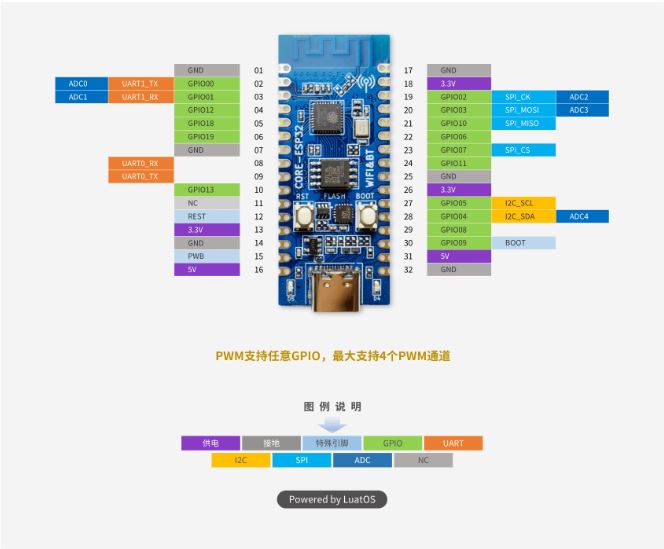
Pin assignment
| Number | Name | Default function after reset | Multiplexing function | Power domain | Pull-down capability |
|---|---|---|---|---|---|
| 32 | Ground | Earthing | |||
| 31 | 5V | 5V power interface, connected to USB VBUS | |||
| 30 | BOOT | GPIO09,Input | BOOTMODE | VDD3P3_CPU | UP/DOWN |
| 29 | IO08 | GPIO08, input, output, high impedance | VDD3P3_CPU | UP/DOWN | |
| 28 | IO04 | GPIO04, input, output, high impedance | I2C_SDA/ADC_4 | VDD3P3_RTC | UP/DOWN |
| 27 | IO05 | GPIO05, input, output, high impedance | I2C_SCL/ADC_5 | VDD3P3_RTC | UP/DOWN |
| 26 | 3.3V | Chip power supply,3.3V | |||
| 25 | Ground | Earthing | |||
| 24 | PB_11 | GPIO11, input, output, high impedance | VDD_SPI | VDD3P3_CPU | UP/DOWN |
| 23 | IO07 | GPIO07, input, output, high impedance | SPI2_CS | VDD3P3_CPU | UP/DOWN |
| 22 | IO06 | GPIO06, input, output, high impedance | VDD3P3_CPU | UP/DOWN | |
| 21 | IO10 | GPIO10, input, output, high-impedance | SPI2_MISO | VDD3P3_CPU | UP/DOWN |
| 20 | IO03 | GPIO03,input, output, high impedance | SPI2_MOSI/ADC_3 | VDD3P3_RTC | UP/DOWN |
| 19 | IO02 | GPIO02, input, output, high impedance | SPI2_CK/ADC_2 | VDD3P3_CPU | UP/DOWN |
| 18 | 3.3V | Chip power supply,3.3V | |||
| 17 | Ground | Earthing | |||
| 16 | 5V | 5V power interface, connected to USB VBUS | |||
| 15 | Printed wiring board | Chip 3.3V power supply control, high level valid, no need to suspend | |||
| 14 | Ground | Earthing | |||
| 13 | 3.3V | Chip power supply,3.3V | |||
| 12 | RESET | Chip reset | VDD3P3_RTC | ||
| 11 | North Carolina | ||||
| 10 | IO13 | GPIO13, input, output, high impedance | VDD3P3_CPU | UP/DOWN | |
| 09 | U0_TX | GPIO21, input, output, high impedance | UART0_TX | VDD3P3_CPU | UP/DOWN |
| 08 | U0_RX | GPIO20, input, output, high impedance | UART0 _RX | VDD3P3_CPU | UP/DOWN |
| 07 | Ground | Earthing | |||
| 06 | IO19 | GPIO19, input, output, high-impedance | USB_D+ | VDD3P3_CPU | UP/DOWN |
| 05 | IO18 | GPIO18, input, output, high impedance | USB_D- | VDD3P3_CPU | UP/DOWN |
| 04 | IO12 | GPIO12, input, output, high impedance | SPIHD | VDD3P3_CPU | UP/DOWN |
| 03 | IO01 | GPIO1, input, output, high impedance | UART1_RX/ADC_1 | VDD3P3_CPU | UP/DOWN |
| 02 | IO00 | GPIO0, input, output, high impedance | UART1_TX/ADC_0 | VDD3P3_CPU | UP/DOWN |
| 01 | Ground | Earthing |
- Any GPIO pin can be used as a PWM pin, and the number corresponds to that of the GPIO pin, but only 4 PWMs can be activated at the same time. Please note
| LEDNumber | Corresponds to GPIO | Pin function | Description |
|---|---|---|---|
| D4 | IO12 | GPIO12 Configuration | Active High |
| D5 | IO13 | GPIO13 Configuration | Active High |
| Taster | Pin Function | ** Description** |
|---|---|---|
| BOOT/GPIO9 | When the key is pressed, the chip enters download mode | Active low |
| RST | When the key is pressed, the chip resets. | Active low |
CH343 USB
A CH343 driver must be installed for operation via the USB port.
Miscellaneous
MicroPython
Das Board scheint MircoPython fähig zu sein. Danke an MK.
https://micropython.org/download/ESP32_GENERIC_C3/
Verwandte Beiträge
Sources
https://luatos.com/en_us/page/home.html
https://wiki.luatos.org/chips/esp32c3/board.html
https://www.wch.cn/downloads/CH343SER_EXE.html
https://gitee.com/openLuat/luatos-soc-idf5
https://micropython.org/download/ESP32_GENERIC_C3/
| Date | Change | Author |
|---|---|---|
| 26.01.2024 | Post created | Suffocation |
This board is also suitable for MicroPython. There is a corresponding display with a directional pad for this.