Last updated on 1 April 2025 by Suffocation
Soll eine IDE Festplatte an einen alten XT Computer angeschlossen werden, oder wird eine Größere Festplatte für den 386er benötigt kann man „einfach“ ein Bios neu schreiben oder den Computer durch einen neuren ersetzten. Da beides meist keine Option ist gibt es zum Glück das XT-IDE Projekt.
Schon kann der XT Computer mit neuen Festplatten zu versort werden oder und AT-Computer größere Festplattenkapazitäten erkennen. Die XT-IDE Software wird wie der Name schon sagt in ein ROM geschrieben, diese kann auf eine Netzwerkarte, auf einer eigens dafür vorgesehenen Karte oder sogar einem neu gebauten IDE Controller aufgedrückt werden.
In diesem Beitrag wird der Einsatz des XT-IDE Bios beschrieben und auf einige Kartenlösungen in anderen Beiträgen wird verwiesen.
Links to the project
Views
Facts
- Ersetzt nicht das eigentlich Bios sondern ersetzt nur die IDE Controller Funktionalität.
- Kann den Code des eigentlichen Bios überdecken (HDD im Bios deaktivieren).
- Es gibt vorgefertigte Bios Version die auf ein Rom gebrannt werden können oder per Makefileanpassung kann eine eigene Version erstellt werden
- The BIOS can be programmed onto EE/UE PROMs such as 27C64, 27C256, 28C64, 28C512…
- Das Bios benötigt eine Hardware wie eine Steckkarte, IDE Controller oder eine Netzwerkkarte mt ROM Sockel.
- Je nach ROM Type und Steckkarten kombination kann das EEROM auf der Karte programmiert werden oder muss extern programmiert und gelöscht werden.
Hardware Projects
Glitchwork rev 4
Monotech XT-CF-Mini
https://github.com/monotech/monotech_xt-cf-mini
XT- CF-Lite
https://github.com/skiselev/xt-cf-lite-v4
ISA ROMs
Zwei Versionen, eine Programmierbar mit Umschalter für 8kB und 32kB EEPRoms die andere nur für 27C256 UEPROMs geeignet.
https://www.vogons.org/viewtopic.php?t=82499
Reconstructed
I've replicated some of the projects, see below under related projects.
ROM on the network card
Es ist auch möglich das XT-IDE Bios auf ein Rom zu flashen und auf den freien ROM-Steckplatz einer Netzwerkkarte zu stecken. Hierbei muss beachtet werden, dass das ROM per Jumper oder Konfigurationtool aktiviert, die richtige Größe angegeben wird und die Startspeicheradresse definiert wird. Auch arbeiten die Netzwerkkarten meist nur mit UV Löschbaren roms wie dem 27C64 zusammen. Diese können dann nur externen EPROM Programmer programmiert werden. Evtl gibt es hierfür aber einen funktonierenden EEPORM Ersatz von WINBOND dann kann man sich das Beleuchten für das Löschen sparen.
Programming
Build XT-IDE BIOS
Die Quellen der XT-IDE sind schnell selbst gebaut, man benötigt nur ein paar Programme und schon wird der eigene Rechner zum Bios-Assemblierer. Beschrieben ist das Ganze unter folgenden Link:
https://xtideuniversalbios.org/wiki/BuildInstructions
Im Grunde müssen die folgenden Tools installiert werden. Danach überprüfen ob sie auch in den Umgebugnsvariablen stehen und einmal neustarten.
- TortoiseSVN (or any SVN client)
- MinGW (only mingw32-make.exe is needed)
- NASM
- UPX (optional)
- Strawperry Perl (optional)
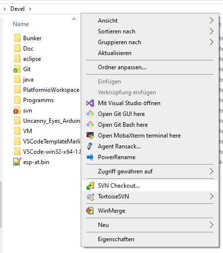
Per SVN die Sourcen holen. Dazu rechtklick mit der Mouse in ein gewähltes Zielverzeichnis und SVN Checkout wählen.
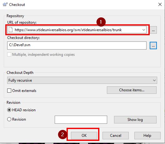
Enter the following URL and check out:
https://www.xtideuniversalbios.org/svn/xtideuniversalbios/trunk
Commandline öffnen und ins Verzeichnis wechseln. Dort den mingw32-make Befehl ausführen und alles sollte bauen.
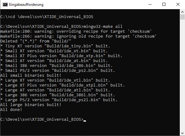
Die Binärdeiten für das Biosrom sind dann im Verzeichnis build zu finden.
Build custom XT-IDE BIOS
Hierfür müssen die beiden folgenden Variablen in der Make Datei (makefile im XTIDE BIOS Ordner) gesetzte werden.
DEFINES_CUSTOM =
BIOS_SIZE_CUSTOM = ?
Zusätlich habe ich noch die Konstate DEFINES_COMMON_CUSTOM eingefügt da ich das Powermanagement entfernt habe. Meine Variante der Konfiguration sieht wie folgt aus:
DEFINES_COMMON_CUSTOM= MODULE_STRINGS_COMPRESSED MODULE_HOTKEYS MODULE_8BIT_IDE MODULE_EBIOS MODULE_SERIAL MODULE_SERIAL_FLOPPY NO_ATAID_VALIDATION CLD_NEEDED EXTRA_LOOP_UNROLLING_SMALL MODULE_BOOT_MENU MODULE_8BIT_IDE_ADVANCED MODULE_COMPATIBLE_TABLES EXTRA_LOOP_UNROLLING_LARGE

DEFINES_CUSTOM = $(DEFINES_COMMON_CUSTOM) USE_386 MODULE_ADVANCED_ATA MODULE_W


#27C256
BIOS_SIZE_CUSTOM = 32768
The BIOS can then be built with the following command:
mingw32-make customDie Binärdeiten für das Biosrom sind dann im Verzeichnis build zu finden.
Configuration tool build
Das Konfigurationstool xtidecfg.com wurde bereits mit der letzten SVN Checkout geholt. Es befindet sich im Verzeichnis XTIDE_Universal_BIOS_Configurator_v2. In das Verzeichnis wechseln und make ausführen.
mingw32-make xtThe file xtidecfg.com can be found in the build directory. There are further options for building the tool:
| Everything | clear, release | Bolt release |
| at | – | AT Version |
| xtplus | – | Extended instruction set for 80188/80186/V20/V30 |
| next | – | XT version instruction set on 8088/8087/V30 |
| Clean | – | Alles aufräumen für einen neuen build |
| Release | next | UPX Compression |
| xt_unused | next | Optimised, don't use, remove code |
Installation
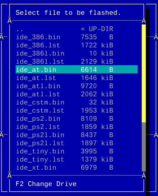
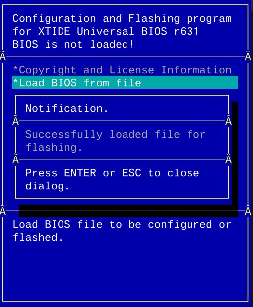
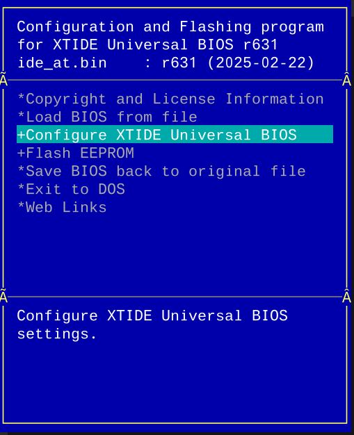
Bevor das Bootrom gebrannt wird, sollte das Rom über das tool konfiguriert werden. Hierfür benötigt man einen Rechner, am besten den, der das Rom später verwende soll. Dort wird dann das Programm xtidecfg.com aufgerufen.
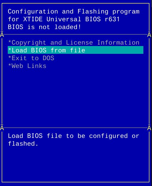
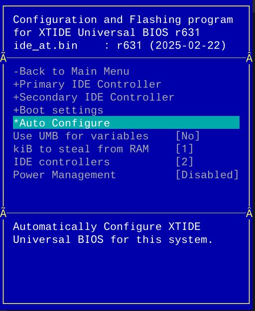
(*) Autoconfig funktioniert nur auf dem original Rechner auf dem man das XTIDE Rom verwenden möchten, ansonsten müssen die Einstellungen, wie zum Beispiel die Adresse des IDE Controllers, manuell vorgenommen werden.
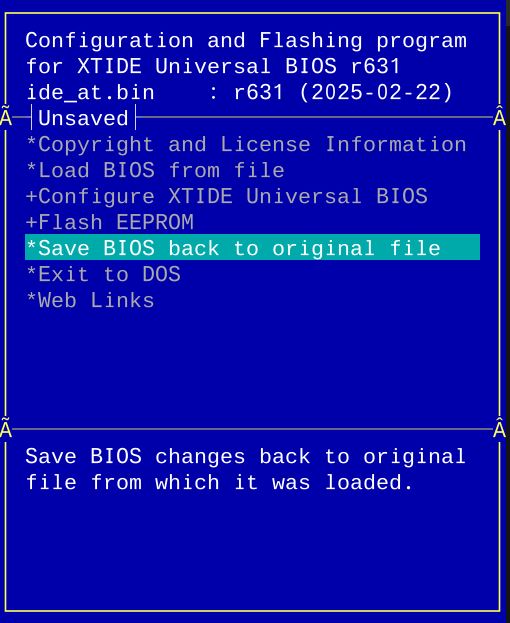
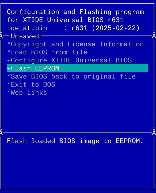
Danach die Datei nehmen und auf das ROM brennen. Sollte ein EEPROM verwendet worden sein und es wird von der Software unterstützt kann es auch direkt über den eingestgeckte Karte programmiert werden.
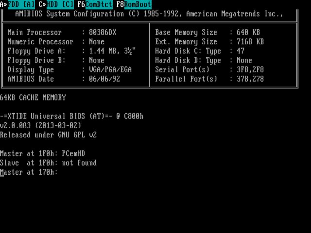
Beim nächsten Booten mit eingestecken rom sollte XTIDE nach der Boardeigenen Biosinitialisierung angezeigt werden.
Problems
XTIDE is not found on boot
- Meist ist dies auf einen Adress-Konflikt entweder mit den ROM oder es wurde nicht die richtige HDD Controller Adress angeben. Auch wenn der Controller nicht gefunden wird, wird XTIDE einfach nicht angeigt. Alle Adressen nochmal überprüfen, auch die Jumper auf den ROM- und dem Controllerboard prüfen. Als guter Wert für die ROM Adresse hat sich C800 und D800 bewährt.
- Falsche ROM verwendet manche EROMs und EEPROMS sind nicht kompatibel. Auch können Karten immer nur die angegebenen EPROM Typen unterstützen. Ich hatte Beipielsweise ein 27C256 mit einem 28C256 ersetzt was aber nicht funktioniert weil das Pinout an zwei Stellen abweicht. Hier muss ein 27C257 verwendet werden ;).
- Beim Rom auf der Netzwerkkarte, darauf achten, dass es aktiv ist, die Größe und die Adresse richtig gesetzt ist.
Controller not found
Sollte wiedererwarten die XTIDE angezeigt werden aber es gibt den Fehler Controller nicht gefunden, so stimmt die Adresse/Typ des IDE Controllers nicht, diese nochmal im Tool überprüfen und das ROM neu flashen.
Checksum Error
XTIDECONF wurde nicht ausgeführt, dieses berechnet die Checksummer und setzt sie. Tool ausführen und ROM neu flashen.
Rom lässt sich nicht über XTIDECFG Flashen
Falsche Rom Version, zum Beispiel lässt sich das AT28C64-B flashen aber das AT28C64 nicht. Versucht man das AT28C64 zu flashen funktioniert die Version auf diesem danach nicht mehr und der EPRROM Programmierer muss angeworfen werden.
Miscellaneous
—
Conclusion
Ein Tolles Projekt. Ich hatte anfänglich ein paar Probleme, dass die XT-IDE nicht gefunden wurde oder das BIOS nicht richtig konfiguriert war. Wenn aber weiss wie es geht und die Fallstricke gefunden und gelöst hat geht es ganz einfach. Leider habe ich diese kleinigkeiten nur in wenigen Youtube Videos gefunden, bzw. erst nachträglich die Details gesehen die nötig gewesen wären. Aber was soll das Jammern, es is geglückt und wenn man die richtigen (E/EE/UE) PROMS nimmt klappt das alles auch. Achtet bei den Projekten darauf welcher ROM-type benötigt wird. Dies ist wichtig damit alle Funktioniert.
Verwandte Beiträge
- Retro Project – ISA Boot EEPROM Card
- Retro Project – Mini ISA ROM Card
- Retro Project – XT-CF-Lite Version 4.1
Sources
https://github.com/glitchwrks/xt_ide
https://users.glitchwrks.com/~glitch/2017/11/23/xt-ide-rev4
https://www.minuszerodegrees.net/xtide/XT-IDE%20-%20Basics.htm
https://www.minuszerodegrees.net/xtide/rev_4/XT-IDE%20Rev%204%20-%20general.htm
https://www.retrospace.net/infoseiten/readm.php?id=66
https://users.glitchwrks.com/~glitch/2017/11/23/xt-ide-rev4
https://www.lo-tech.co.uk/wiki/XTIDE_Universal_BIOS
Log
| Date | Description |
|---|---|
| 15.07.2024 | Plates ordered with XT ROM from DocWilde Retronics |
| 23.07.2024 | Bauteile aufgelötet |
| 22.02.2025 | Infos zum Bios Baus hinzugefügt |
| 23.02.2025 | Introduction written |
| 30.03.2025 | XT ide im PCem simuliert und screenshots gemacht. Evtl. Screenshots von richtiger Hardware noch einfügen. |
| Date | Change | Author |
|---|---|---|
| 31.07.2024 | Post created | Suffocation |