Last Updated on 18. October 2026 by SuffocationLink status: OK
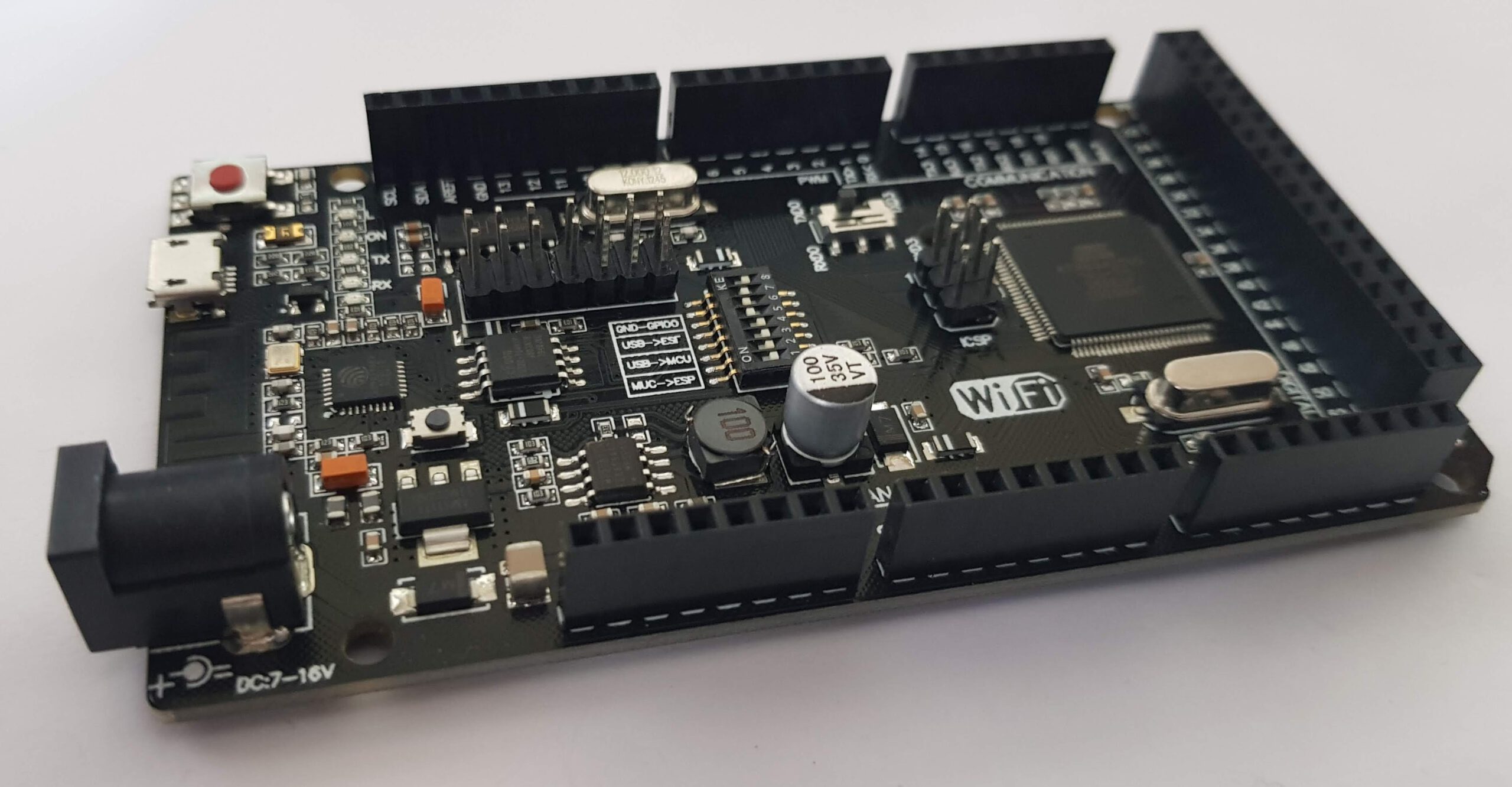
Es handelt sich hierbei um ein hybrides Board aus Atmega 2560 und einem Espressif Chip (ESP8266) für die WLan Kommunikation.
View
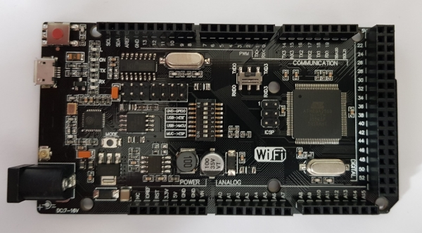
Overview
| Mega + WiFi (ATmega2560 + ESP8266) | |
|---|---|
| Processor | ATMEGA 2560 + ESP8266 |
| Kernel | 1/1 |
| Tact | 16 / 160 MHz |
| Flash | 256 KB / 32 Mbit |
| SRAM | 8 KB |
| EEPROM | 4 KB |
| Digitale Pins | 54 |
| Analoge Eingänge | 16 |
| PWM-Pins | 15 |
| Interrupt-Pins | 6 |
| UART | 4 |
| SPI | 1 |
| I²C | 1 |
| WLAN | 802.11 b/g/n (2,4 GHz) · WPA / WPA2 · WEP / TKIP / AES |
| USB | 1 Micro |
| Operating voltage | 5 V |
| Input voltage | 7-16 V |
| Abmessungen | 101.52 x 53.3 mm |
Board features
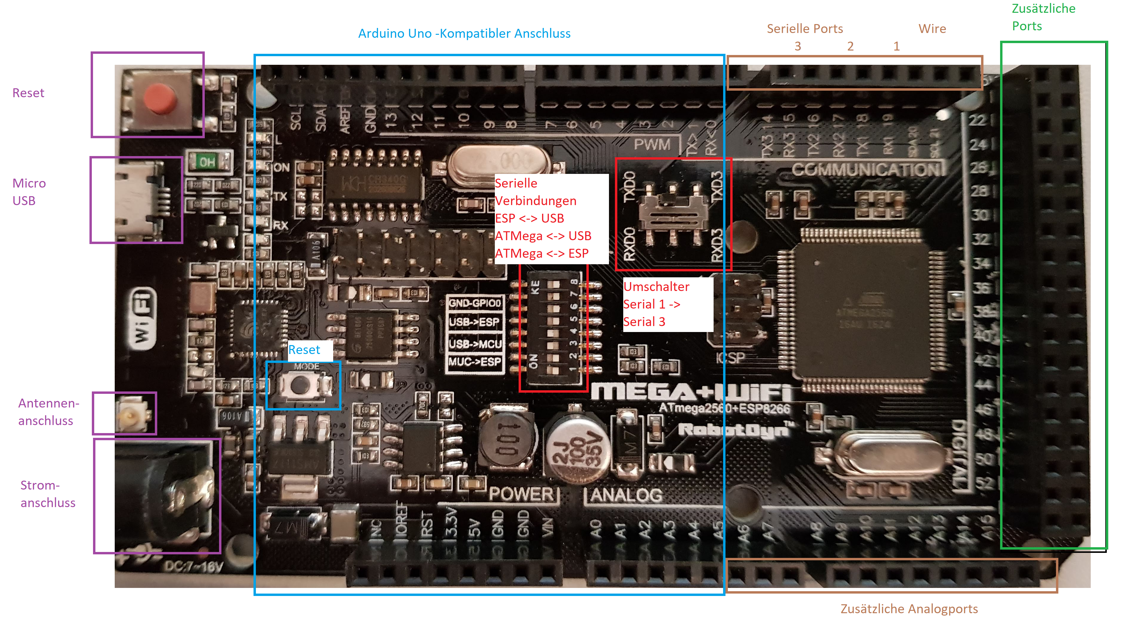
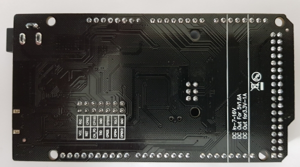
Additionally, some of the ESP pins are brought out. The labelling can be found on the back of the board.
DIP Switch Settings
| 1 | 2 | 3 | 4 | 5 | 6 | 7 | |
| ATMega ESP | An | An | Australia | Australia | Australia | Australia | Australia |
| USB ATMega | Australia | Australia | An | An | Australia | Australia | Australia |
| USB ESP Firmware | Australia | Australia | Australia | Australia | An | An | An |
| USB ESP Com. | Australia | Australia | Australia | Australia | An | An | Australia |
| No connections | Australia | Australia | Australia | Australia | Australia | Australia | Australia |
Special Pin Assignments
| Function | Pins |
| Interrupt | 2, 3, 18, 19, 20, 21 |
| Serial port 1 Serial port 2 Serial port 3 Serialport 4 | 0 (Receive), 1 (Transmit) 19(RX), 18(TX) 17 (RX), 16 (TX) 15 (RX), 14 (TX) |
| LED | 13 |
Closer inspection
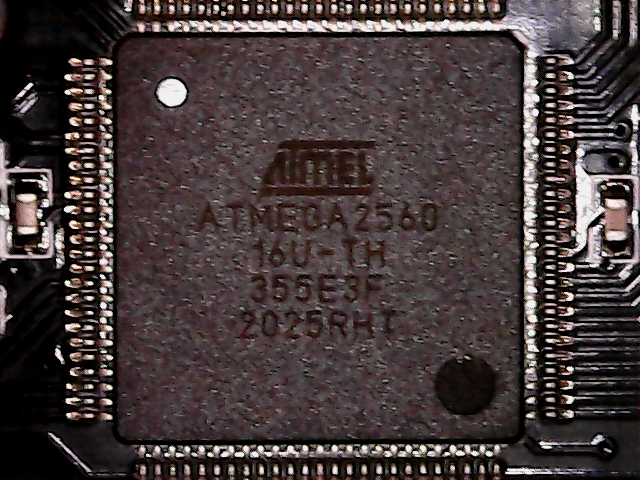
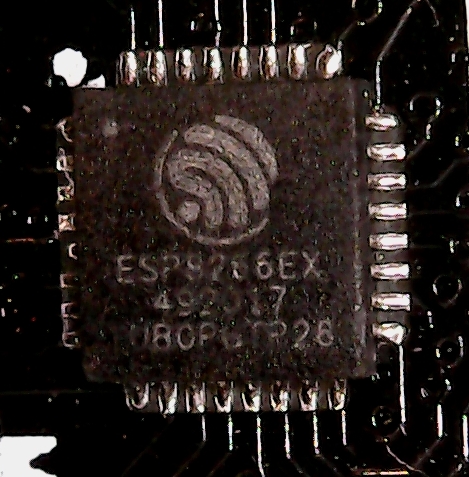
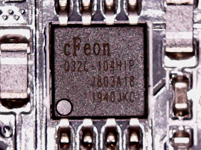
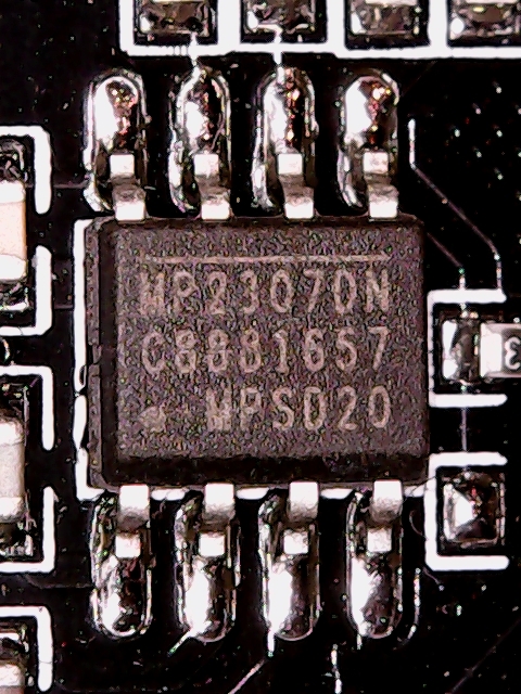
Here are a couple of snapshots with the microscope.
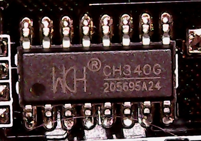
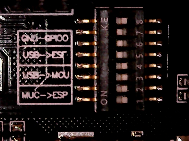
Programming environment
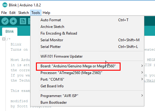
Mega Settings
Dipschalter 3,4 auf ON, Rest auf OFF
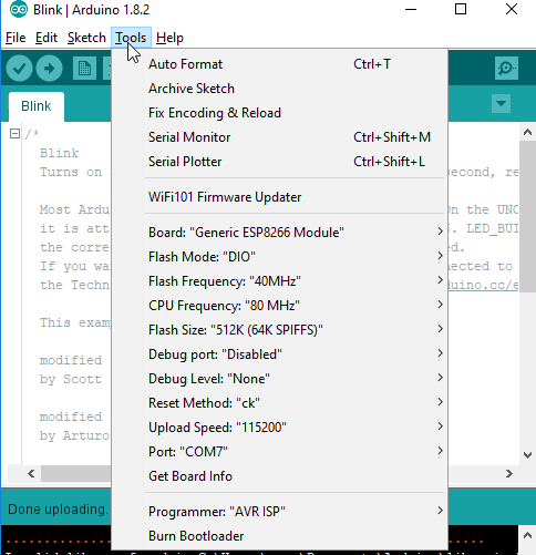
ESP Settings
Possibly, before that, Setting up the ESP8266 programming environmentLink status: Unknown. I used version 2.7.1 of the board drivers here.
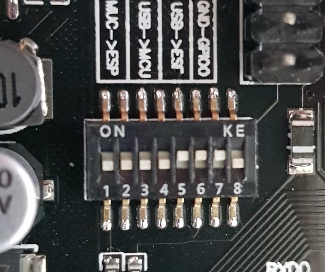
Dipschalter 5,6,7 auf ON, Rest auf OFF. Sollte das Programmieren nicht beginnen, ist ein Reset des Boards nötig. Das Spielen mit der Reset Methode im Menü brachte hier leider keine Besserung.
Test Programme
Als Testprogramme können die des hier gelinkten Beitrags verwendet werden.
Miscellaneous
Using AT-Lib
Wenn man noch nicht so genau weiß, wo die Reise hingeht und für was der ESP auf dem Board gebraucht wird, kann man erst einmal eine Maximalkonfiguration aufspielen. D. h. man spielt die sogenannte AT-Firmware auf, die durch Steuerkommandos (die komischerweise alle mit AT beginnen) konfiguriert wird, ohne jedes Mal neu programmiert werden zu müssen. Wer jetzt glaubt, vom Regen in die Traufe zu kommen und AT Kommandos lernen zu müssen, hat Glück, es gibt ein Gegenstück für den Arduino. Ein paar Klassen erlauben es, den ESP mit einfachen Methodenaufrufen zu steuern, ohne die AT Kommandos verwenden zu müssen. Somit sind die Ziele:
- Installing the AT firmware on the ESP
- Create a program on the Arduino which uses the ESP as a Wi-Fi adapter
HINWEIS: Schaut mal vorab, ob nicht schon die AT Firmware auf dem ESP vorhanden ist. Solltet ihr sie überschrieben haben, kein Problem, hier erfahrt ihr, wie ihr sie wiederherstellen könnt.
Den Prepare ESP
Den ESP selbst auf Programmierung einstellen:
For the ESP, we need a version of the AT library. This is available as a binary file on the Espressif homepage.
https://www.espressif.com/en/support/download/atLink status: OK
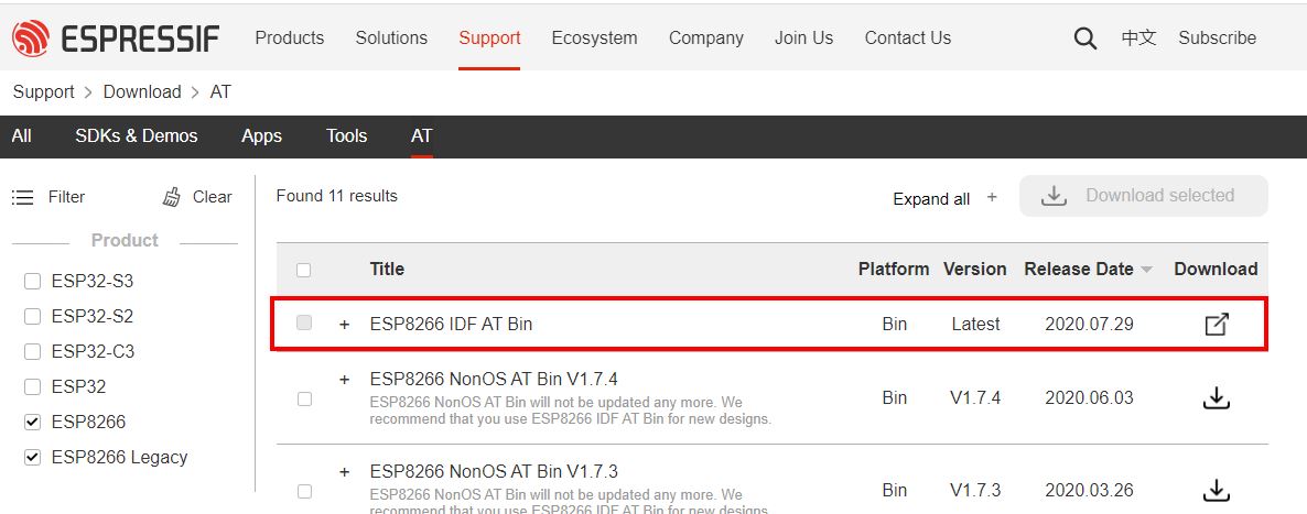
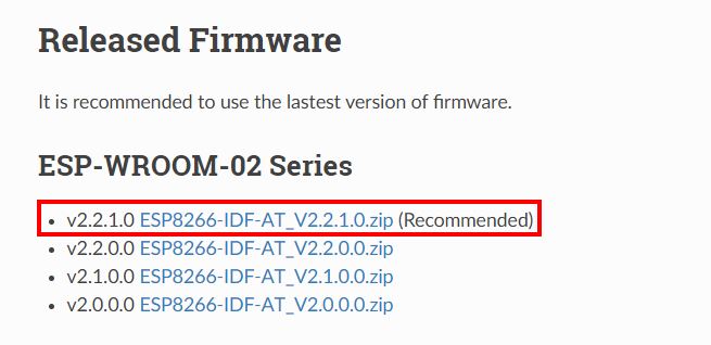
If the chosen firmware doesn't work, try older versions. I also tried several and ended up with version 1.6 in this setup.
Zum Flashen der Binärdatei auf den ESP kann jedes beliebige Tool verwendet werden, hier das vom Hersteller.
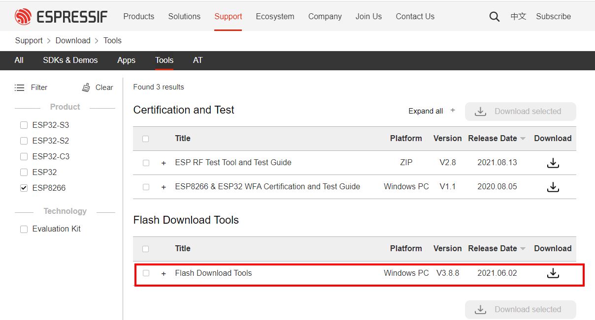
Tool und Binärdatei entpacken. Geladen wird mit der 1.6 Version wie folgt. In den README Dateien der Zips ist meist beschrieben, wie diese zu flashen sind (hat bei mir alles nicht funktioniert, habe nach unzähligen Versuchen eine Kombi gefunden, die bei diesem Board funktionierte).
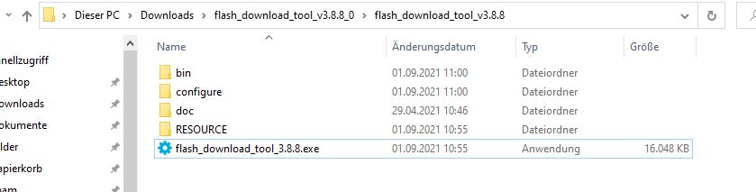
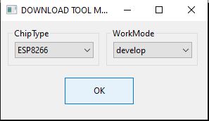
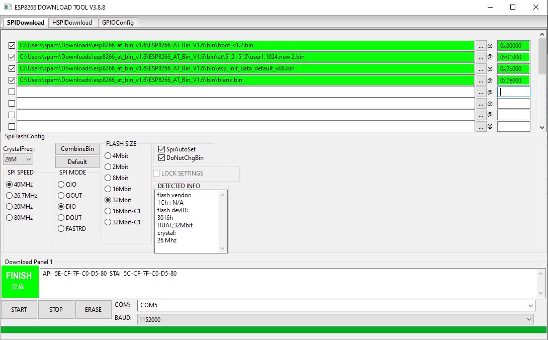
Dateien auswählen, Speicherbereiche eingeben, Einstellungen anpassen und noch die richtige Verbindung zum Board wählen. Danach auf Start und warten, was passiert.
Ob die Firmware richtig installiert ist, kann in der Arduino IDE Konsole überprüft werden. (Nicht vergessen, Dipschalter 7 wieder auszuschalten, sonst geht nichts). Baudrate ist 115200, als Zeilenende NL/CR auswählen und oben in die Sendezeile AT eingeben. Kommt ein OK zurück, klappt erstmal alles.
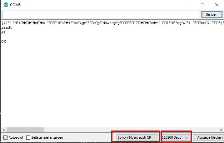
Wer noch mehr über die vorhandenen AT Kommandos wissen will, kann sich auf der folgenden Seite informieren.
https://docs.espressif.com/projects/esp-at/en/latest/AT_Command_Set/index.htmlLink status: OK
Da im Arduino auf das Netzwerk zugegriffen werden soll, möchte ich das vorab mal mit AT Kommandos prüfen:
AT+CWMODE=1 -> Turn on Station Mode
AT+CWLAP -> Netzwerk scannen, gibt ne Liste zurück
AT+CWJAP=“NODES“,“HappyNodes1234″ -> Mit Accesspoint verbinden
Hinweis: Die Zugangsdaten sind nur Beispiele und müssen durch eigene ersetzt werden.
AT+CIFSR -> Get connection information
AT+CWDHCP? -> DHCP enabled? If not, enable with AT+CWDHCP:1

More coming soon....
Externe Antenne anschließen
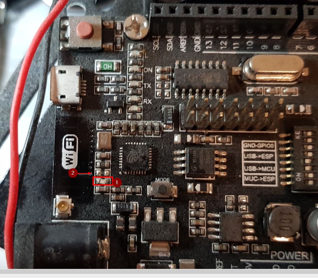
Wie ihr im Bild seht, ist mein Mega+Wifi etwas eingestaubt. Nichtsdestotrotz kam die Frage auf, was zu tun ist, um eine externe Antenne anzuschließen. Hierfür muss die Brücke (0 Ohm Widerstand) aus dem Bild umgelötet werden auf die freie Position (2).
Conclusion
Wer ein Arduino Uno kompatibles Board, eine Menge zusätzlicher Ports und eine WLan Anbindung benötigt, ist mit diesem Board richtig gut bedient. Der Antennenanschluss vergoldet das Board zusätzlich, da hierdurch höhere Reichweiten erreicht werden können.
Zudem ist das Board recht günstig, seitdem der ESP32 draußen ist, wird das Board zum Teil unter 10€ gehandelt (schaue beim schnellen Ali oder beim guten Beng nach 😉 ).
Sources
https://www.arduino.cc/reference/en/language/functions/external-interrupts/attachinterrupt/Link status: Broken
https://www.arduino.cc/en/Hacking/PinMapping2560Link status: OK
https://www.instructables.com/id/Arduino-MEGA-2560-With-WiFi-Built-in-ESP8266/Link status: OK
https://robotdyn.com/catalog/boards/mega_wifi_r3_atmega2560_esp8266_flash_8gb_usb_ttl_ch340g_micro_usb/Link status: Unknown
https://docs.espressif.com/projects/esp-at/en/latest/AT_Command_Set/index.htmlLink status: OK
https://www.espressif.com/en/support/download/atLink status: OK
| Date | Change | Author |
|---|---|---|
| 18.10.2026 | TablePress-Tabelle durch Datenblock aus dem Modell ersetzt | Suffocation |
| 05.10.2026 | Hinweis zu Beispiel-Zugangsdaten ergänzt | Suffocation |
| 04.10.2026 | Rechtschreibung korrigiert: Tippfehler, Kommas, Groß-/Kleinschreibung, Grammatik | Suffocation |
| 03.10.2026 | Log-Liste eingefügt | Suffocation |
| 31.10.2017 | Post created | Suffocation |
Has anyone found a compatible case for the RobotDyn board?
Hi Kai, actually any AT-Mega housing should fit, it's the same form factor. However, you should take a closer look at the distances, e.g. between USB ports and power.
https://www.thingiverse.com/search?q=arduino+mega+&page=1&type=things&sort=relevant
Hello,
I wanted to set up this board with ESP using your guide. Unfortunately, the version you used in your guide is no longer available on the Espressif website. The current version does not have the .bin files you used. Do you know of another download option or can you send me this version via email?
Thank you
Thomas
Hello Thomas, have a look at the page https://robertoostenveld.nl/esp8266-at-firmware/ There are also old ones linked, as far as I know.
Greetings Stefan
P.S. Unfortunately, I no longer have a version on my hard drive.
Hello Stefan,
Thank you very much for the quick reply. I also managed it with the current firmware. DIP switches 5 and 6 are now on, the rest off. AT commands work and the connection to the FritzBox also works. Once the connection is established it is also stable. It just sometimes takes a few board resets until it gets an IP address. Although it is set in the FritzBox that the same IP address should always be assigned.
The problem now is that I can't get a sketch onto the ESP. I downloaded a small sketch for a mini web server to test. Compiling also runs without errors. However, in the Arduino IDE, under the selected board Generic ESP8266, the Programmer is „No Programmer available“. In your instructions above, however, there is one. Naturally, I always receive the message that the sketch cannot be uploaded due to a timeout.
Any clever ideas where the problem might lie?
Thank you
Thomas
Hello Thomas,
I've just checked it on my end. It really doesn't say Programmer anymore, but programming my board is possible. However, with me, DIP switches 5, 6, and 7 must be activated for programming. After programming, remove 7 again. (If the ESP is not already disconnected from the power, reset it again in both cases).
Greetings Stefan
Thank you, good article
I have such a board running to connect RFLink to my MQTT broker via MQTT and WiFi.
I am finding that the stability of the WiFi connection is extremely dependent on the [STAO] situation. I have a WiFi setup based on a Fritz 7560 and two repeaters in a mesh. I am currently using the PCB antenna.
Has anyone successfully connected an external antenna? Does anything need to be re-soldered for this?
Hi, I'm currently on holiday and don't have the board in front of me. But I always thought that mine at least only worked with an external antenna. I can't see an etched antenna on the pictures, nor the characteristic 0 Ohm jumper.
Greetings Stefan
Hey! Very good article, thank you very much. Which version of the esp8266 lib was used? I have 2.7.4 from http://arduino.esp8266.com/stable/package_esp8266com_index.json, many more options that are overwhelming me at the moment.
Hello Michi,
Good tip, you should always include the version number :( I'll improve that straight away. I used version 2.7.1. If no methods have been renamed or new bugs have been added, it should also work with 2.7.4 :).
Hello
Stefan
Very helpful!
Thank you very much!