Last Updated on 10. October 2026 by SuffocationLink status: OK
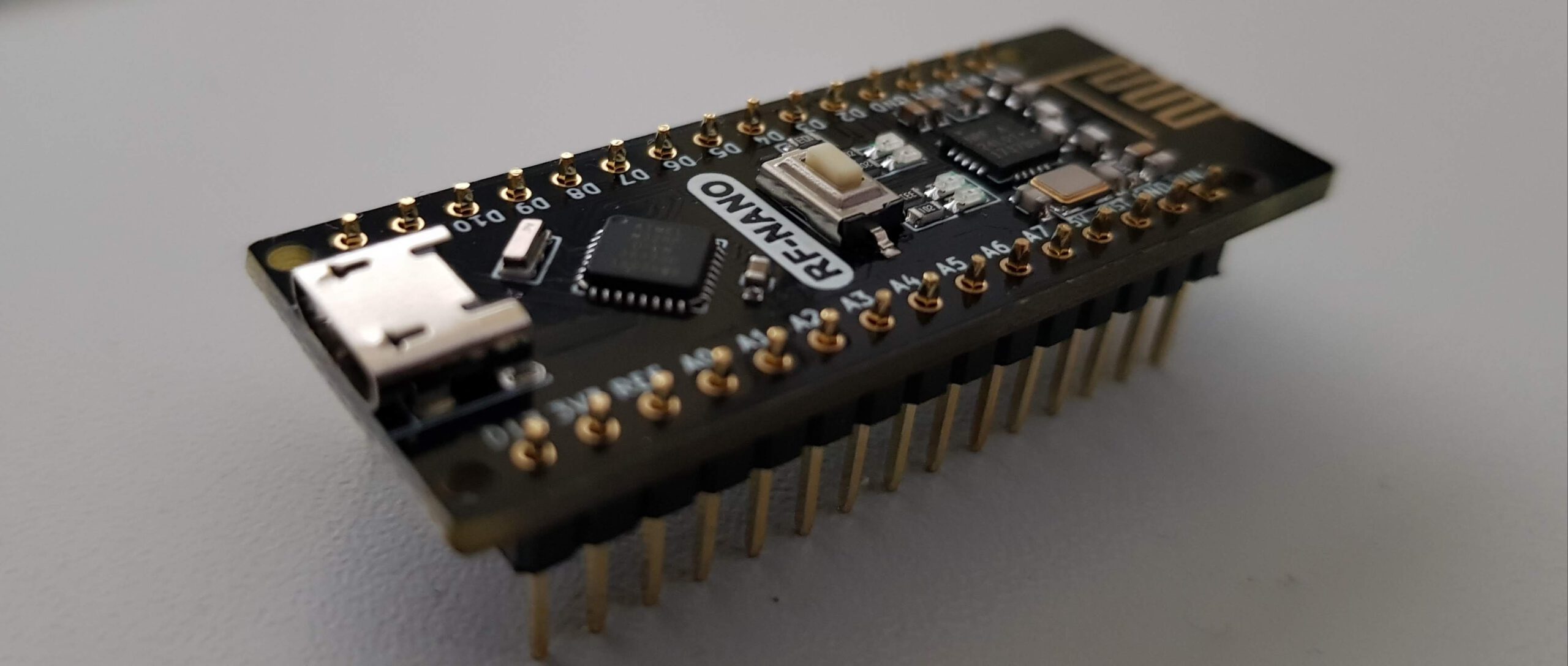
Der RF Nano ist eine Replik des Arduino Nano, zusätzlich verfügt er noch über einen NRF24L01 Baustein, was ihm die RF Kommunikation ermöglicht.
Vorsicht, es gibt unterschiedliche Versionen dieses Nanos, es lohnt sich also genau hinzuschauen.
Facts
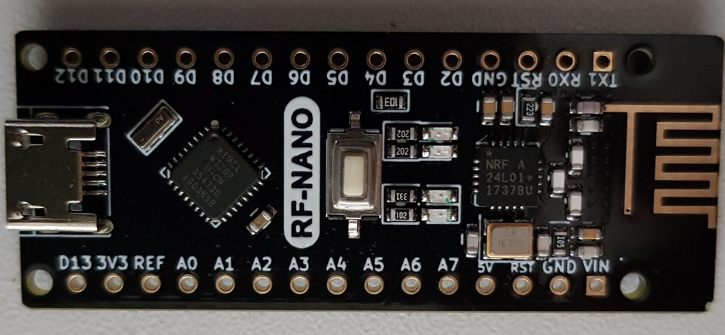
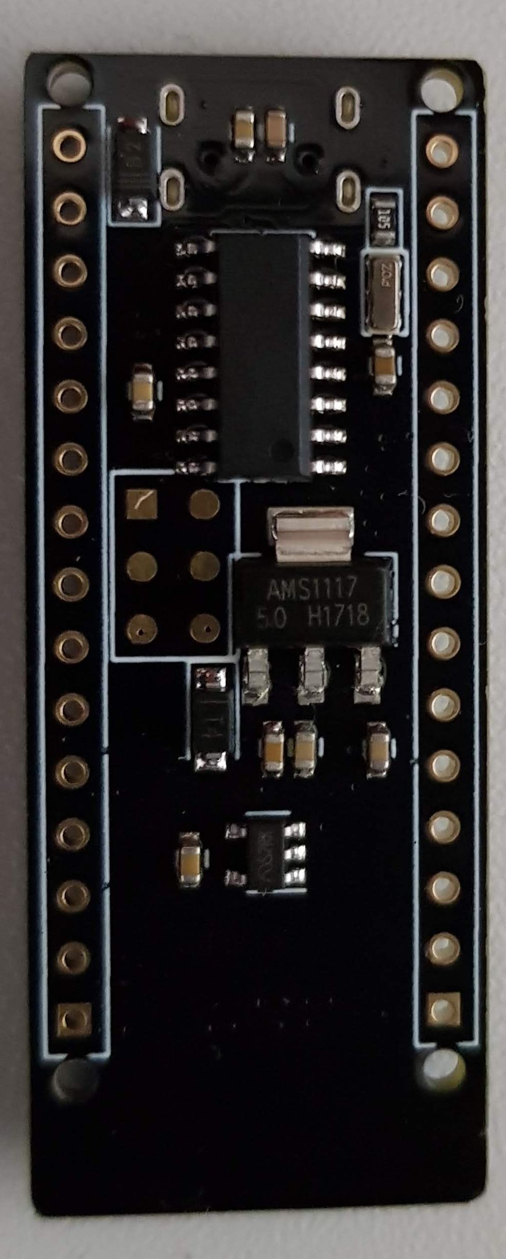
Das Board sieht wie ein gewöhnlicher Nano aus, wenn da nicht die aufgedampfte Antenne (unten) und ein Micro USB anstatt des Mini-USB Anschlusses wären.
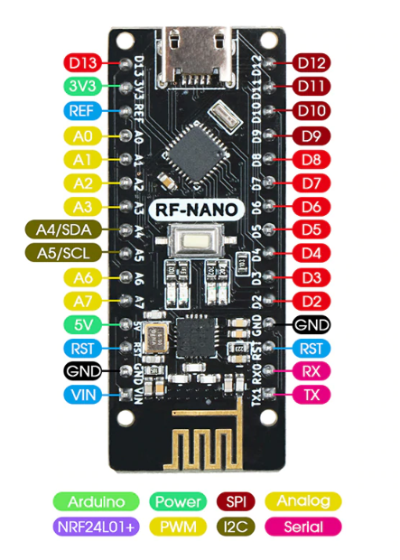
Comparison with standard
I have compared the pin assignment with the standard and it is the same for me. (Please check again, as other imitations might have different pin assignments).
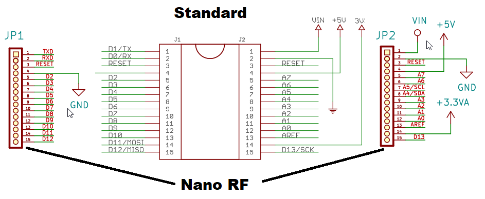
NRF Connections
The pin information is taken from the manufacturer's circuit diagram.
ACHTUNG: Die Pins für CE und CSN sind bei mir, im Gegensatz zu den meisten Beispielen im Netz, vertauscht, es soll aber auch RF-Nanos mit richtiger Pinbelegung geben.
| Description | Pin |
| CE | 10 (9) |
| Counter-Strike: Global Offensive | 9 (10) |
| SCK | 13 |
| MOSI | 4 |
| Miso | 5 |
Areas of application
- Remote control
- Sensor node
- Alles, was miteinander kommunizieren muss.
Views
Programming
Libraries
Manufacturer-used library
Meine bewährte Bibliothek hat beim ersten Test nicht funktioniert, weshalb ich erstmal die des Herstellers ausprobiert habe. So konnte ich den Fehler in meinem Programm finden.
https://github.com/joewalnes/arduino-play/tree/master/lib/MirfLink status: OK
https://github.com/tmrh20/RF24/Link status: OK
Standard RF Library
Hier die Standard-Bibliothek, die ich schon in anderen Projekten verwendet habe.
https://github.com/tmrh20/RF24/Link status: OK
Test programme
Manufacturer's programme
For the first test, I will use the manufacturer's programmes. The source code is available on Github via the following link:
https://github.com/emakefun/emakefun-nano-plusLink status: OK
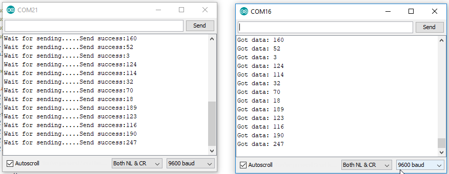
I have acquired two identical Nanos and programmed one as a receiver and the other as a sender. The output is shown in the following image.
Test with RF Library
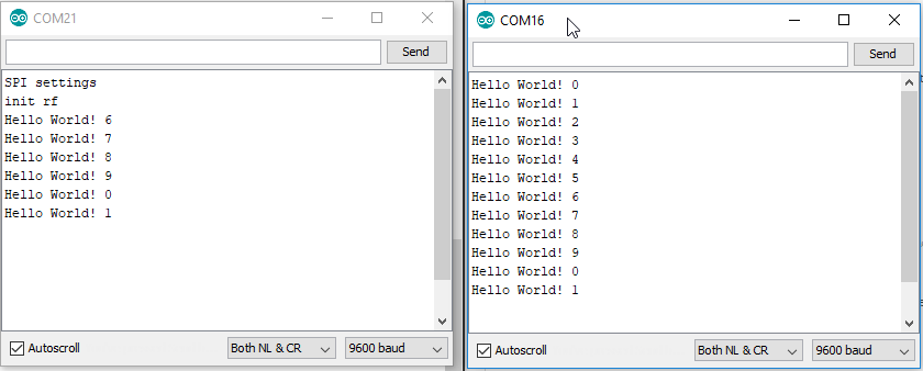
Here's my test program with the RF library. I've simply copied the library files into the project. Here's the code:
Source code Receiver.ino (GitHub GistLink status: OK)
// Nano Remote Receiver
// This programm receives a char array with maximum size 20
// www.fambach.net
//
// Libs:
// https://github.com/tmrh20/RF24/
//
// GPL2
/***********************************************************/
// radio
#include <SPI.h>
#include "nRF24L01.h"
#include "RF24.h"

#define PIN_CE  10
#define PIN_CSN 9

RF24 radio(PIN_CE, PIN_CSN);
byte addresses[][6] = {"007", "001"};

#define SIZE 20
char buf[SIZE];

/***********************************************************/

void setup() {

  Serial.begin(9600);
  delay(4000);

Serial.println("SPI settings");
  SPI.begin();
  SPI.setDataMode(SPI_MODE0);
  SPI.setClockDivider(SPI_2XCLOCK_MASK);

  Serial.println("init rf");
  radio.begin();                      // initialize RF24
  radio.setRetries(0, 15);            // set retries times
  radio.setPALevel(RF24_PA_LOW);      // set power
  radio.openWritingPipe(addresses[0]);
  radio.openReadingPipe(1, addresses[1]);
  radio.startListening();             // start monitoring
}


void loop()
{
  // receive data ;)
  receiveData();
}


void receiveData() {
  if ( radio.available()) {            // if receive the data

    // Read the data payload until we've received everything
    bool done = false;
    while (radio.available())
    {
      // Fetch the data payload
      radio.read( buf, sizeof(buf));

//      for(int i = 0; i < 20; i ++){
//        Serial.print((char)buf[i]);
//      }
      Serial.println(buf);
    }
  }
  else
  {
    // Serial.println("No radio available"); //only for test purpose
  }
}
Source code Sender.ino (GitHub GistLink status: OK)
// Nano Remote Transmiter
// This programm sends Hello World! x (x is an index from 0 to 9)
// www.fambach.net
//
// Libs:
// https://github.com/tmrh20/RF24/
//
// GPL2
/***********************************************************/
// RF
#include <SPI.h>
#include "nRF24L01.h"
#include "RF24.h"

#define PIN_CE  10
#define PIN_CSN 9

RF24 radio(PIN_CE, PIN_CSN); // define the object to control NRF24L01
byte addresses[][6] = {"007", "001"};
int mode = 1;
#define SIZE 20
char buf[SIZE];

void setup() {
  Serial.begin(9600);

  /***********************************************************************/
  // init radio
  radio.begin();                      // initialize RF24
  radio.setRetries(0, 15);            // set retries times
  radio.setPALevel(RF24_PA_LOW);      // set power
  radio.openWritingPipe(addresses[1]);  // open delivery channel
  radio.openReadingPipe(1, addresses[0]);
  radio.stopListening();

}
int i = 0;
void loop() {

  String s;
  s.reserve(20);
  s = "Hello World! ";
  s += i;
  s.toCharArray(buf, SIZE);
  Serial.println(s);

  radio.write(buf,sizeof(buf));

  i++;
  if (i > 9) i = 0;

  delay(1000);
}
Link to the GitHub directory:
https://github.com/sfambach/arduino/tree/master/variants/NanoRF/RFTestLink status: Broken
Remote control test
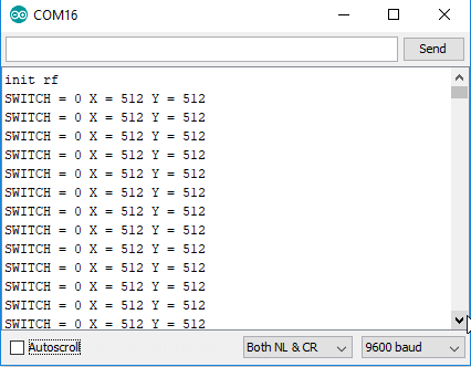
Ich habe bereits ein paar Tests mit NRF Chips gemacht. Unter anderem habe ich eine SunFounder Fernbedienung in Betrieb genommen. Diese verwende ich in diesem Sketch als Basis. Die Software ist gleich zu der im gelinkten Projekt, jedoch habe ich für den Empfänger (der auf dem Nano RF ist) den CS auf Pin 10 und den CSN auf Pin 9 eingestellt.
The current source code can be downloaded from Github
https://github.com/sfambach/arduino/tree/master/variants/NanoRF/SFRemoteTestLink status: Broken
Den Receiver wie oben beschrieben auf den Nano RF spielen. Den Transmitter, so wie er ist, auf die Fernbedienung spielen.
Problems
Initial communication with RF24 failed
Der CE und der CSN Pin sind im Gegensatz zu meinen anderen Projekten vertauscht. CE ist auf Pin 10 und CSN ist auf Pin 9.
ACHTUNG Siegfried berichtet (siehe unten in den Kommentaren), dass er einen Nano mit richtiger Pinbelegung bekommen hat also CSN auf 10 und CE auf 9!
Windows does not recognise Nano
Maybe install a CH340 USB driver.
https://github.com/emakefun/emakefun-nano-plus/tree/master/RF-Nano/CH340_DriverLink status: Broken
Nearby receivers won't connect
Rachid beschreibt (siehe unten in den Kommentaren), dass er Probleme bei nahe beieinander stehenden Sender und Empfängern hat und die Initialisierung schiefläuft. Bei ihm hat geholfen, die Power hochzusetzen. Bei den diskreten nRF Modulen kann dies zu Problemen mit der Spannungsversorgung führen.
 radio.setPALevel(RF24_PA_LOW);   // set power
// exchanged for
radio.setPALevel(RF24_PA_MAX);
Kanal setzen
Jens beschreibt (siehe unten in den Kommentaren), dass es von Vorteil sein kann, den Kanal manuell zu setzen. Dieser wird in der begin Methode der RF lib zwar auf 76 gesetzt, zur Fehlerbehebung kann dies jedoch eine Lösung sein, diesen in Sender/Empfänger gemeinsam auf einen anderen Wert zu setzen.
void setup(){
  ...
  radio.setPALevel(RF24_PA_LOW);
  radio.setChannel(99); // Set channel
  ...
}
Conclusion
Ich bin begeistert, ein Nano mit einem RF Chip, alles, was man benötigt, um ferngesteuerte Bots zu bauen. Hier kann man sich das Verdrahten sparen. Über die Stabilität und das Verhalten im Einsatz kann ich noch nichts berichten. Der erste Test war hierfür zu simpel.
Related Posts
- Funduino JOYSTICK V1.ALink status: OK
- NRF RC CarLink status: OK
- Sunfounder nRF24 Remote ControlLink status: OK
Sources
https://github.com/emakefun/emakefun-nano-plusLink status: OK
https://github.com/tmrh20/RF24/Link status: OK
https://github.com/emakefun/emakefun-nano-plus/tree/master/RF-Nano/CH340_DriverLink status: Broken
https://github.com/nulllaborg/lgt-rf-nanoLink status: OK
| Date | Change | Author |
|---|---|---|
| 10.10.2026 | Gist-Einbettung durch Code-Block ersetzt (Gist als Quelle verlinkt) | Suffocation |
| 04.10.2026 | Rechtschreibung korrigiert: Tippfehler, Kommas, Grammatik | Suffocation |
| 03.10.2026 | Log-Liste eingefügt | Suffocation |
| 06.08.2019 | Post created | Suffocation |
I have two RF-Nano Clones V1229 from AliExpress (supposedly V3.0). You can recognise V1x by the lack of an antenna socket.
They work with RF24 SendRadio(10,9) using the example scripts from the manufacturer's GitHub repo. https://github.com/emakefun/rf-nano. The set transmission power is irrelevant, at least as long as the nanos are next to each other.
Thank you for your contribution
Hello Stefan,
I received an RF Nano from China today (V3.0) and found that it only works when I specify CE on D9 and CSN on D10 in the program. With the variant mentioned in various datasheets and by you, no transmission is established.
Greetings Siegfried
Hi Stefan,
Thanks for the info. I think that in the example with the RF library, the channel should still be set, e.g. after the transmit power:
...
radio.setPALevel(RF24_PA_LOW);
radio.setChannel(99); // NEW
,,,
Kind regards,
Jens
Hello Jens,
Thank you for your suggestion. The channel is set to 76 in the begin method of the RF library. I have nevertheless documented it in the code to fix potential problems.
Greetings from Hesse
Stefan
Hello Stefan,
I was pleased that you replied so quickly. I had problems, probably because I was using the transmitter and receiver independently. However, I had also included the RF24 library via the Arduino library manager.
Kind regards,
Jens
Good day,
I've actually followed everything as described. CE and CSN pins are also correct. The wiring is clean so far. Unfortunately, my output always stops at „SPI settings".
init rf“ and that's it. Where could my problem lie?
Thank you very much.
Hello Rachid, I don't know your exact test setup, for example what your counterpart is. But the RF modules, especially the newer ones, are very critical regarding the supply voltage. If that's an option, try connecting the Nano to an external power source.
You can also play around with the settings. Perhaps swap the PIN for CS and CSN again.
Hello
Stefan
Hello Stefan,
Thank you very much for the quick reply.
I have now swapped PA_LOW with PA_MAX and then it worked. Sometimes too slow and sometimes just right. But I think it's only because the receiver and transmitter are too close.
Thank you very much.
Very good,
Rachid
Hi Rachid,
Thank you for your solution. It surprises me that more power and in short distances changes something, I will include it in the troubleshooting.
Greetings from Hesse
Stefan