Last Updated on 3. October 2026 by SuffocationLink status: OK
Mit Hilfe dieser Zusatzplatine kann der Arduino über das WLAN kommunizieren. Die Platine hat einen ESP8266 Microcontroller on Board, welcher die Netzwerkkommunikation übernehmen kann. Bei Auslieferung sollte auf dem ESP eine Firmware von AI Thinker aufgespielt sein. Wie man dies herausfindet und vieles mehr, habe ich in diesem Beitrag so kompakt zusammengefasst.
Im Netz wird oft bemängelt, dass es anscheinend keine Dokumentation zu dieser Platine gibt. Auch die Herstellerseite war zum Zeitpunkt der Erstellung dieses Beitrages nicht verfügbar. Dennoch gibt es einige Versuche zur Dokumentation, die mir sehr geholfen haben. Alle sind wie immer unter dem Kapitel Quellen gesammelt verlinkt.
Man könnte sich nun fragen, warum einen ESP, der an sich schon recht leistungsstark ist, auf einen Arduino packen, der kein Wifi kann. Nun, hierfür sprechen die folgenden Argumente:
- Der Arduino kann 5V Peripherie bedienen, der ESP direkt nur 3.3V
- Der Arduino hat mehr verwendbare IOs und mehr analoge Ports
- There are more add-on boards for the Arduino than for the ESP.
- Wenn man nur Wifi braucht, aber nicht auf ESP Programmierung umsteigen will, bietet dies eine gute Lösung
Addendum: Es gibt mindestens zwei Platinen dieser Art. Das Original, welches keine Probleme machen sollte und das Plagiat, welches ich hier beschreibe ;).
Facts
- Arduino Uno/Leonardo compatible add-on board.
- Houses an ESP8266 Wi-Fi module
- Der ESP8266 ist mit einer nicht näher definierten Firmware geflasht (Weiteres später)
- The ESP's UART is set to 115200 baud
Views
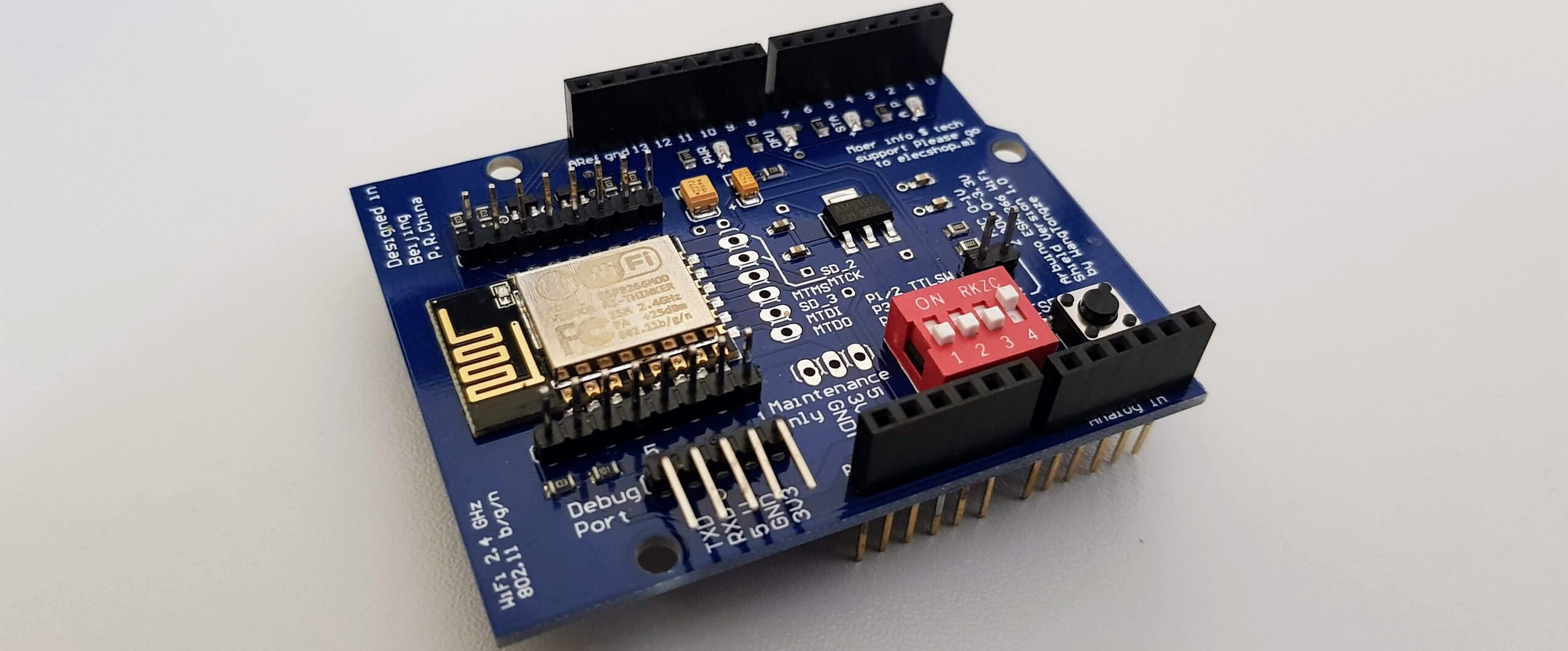
So sieht die Platine aus, man erkennt gut den ESP auf der linken Seite der Frontansicht. Seine Anschlüsse sind zusätzlich über Pins herausgeführt, so dass man diese auch nutzen könnte. Unterhalb des ESPs ist dessen serielle Schnittstelle herausgeführt. Rechts neben dieser befindet sich ein Dipschalter (mehr dazu später), gefolgt von einem Resetschalter für den ESP.
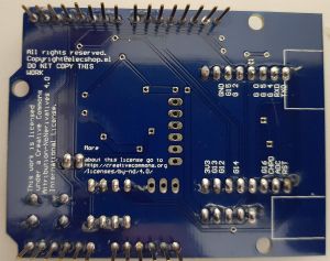
ESP8266 add-on board from below 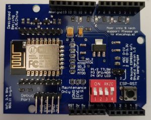
ESP8266 add-on board from above 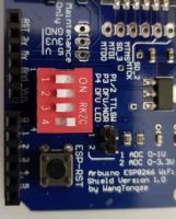
ESP8266 add-on board DIP switch 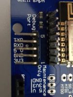
ESP8266 Add-on board debug port
Analyse
Ich habe mich entschlossen, da die Dokumentation so spärlich ist, mal ein Analyse Kapitel einzuflechten. Hier beschreibe ich, was ich zur Erkundung der Zusatzplatine so gemacht habe.
DIP switch
I found the DIP switch settings online:
| Switch | Description |
| 1/2 | Only together do we switch, connects the seriellen Port des Arduino mit dem ESP (funktioniert nicht beim Plagiat) |
| 3 | Aktiviert den Bootloader, Brücke between Mass and GPIO 0 |
| 4 | DFÜ LED zeigt die Aktivitäten am seriellen Port. (Function currently unknown) |
Firmware
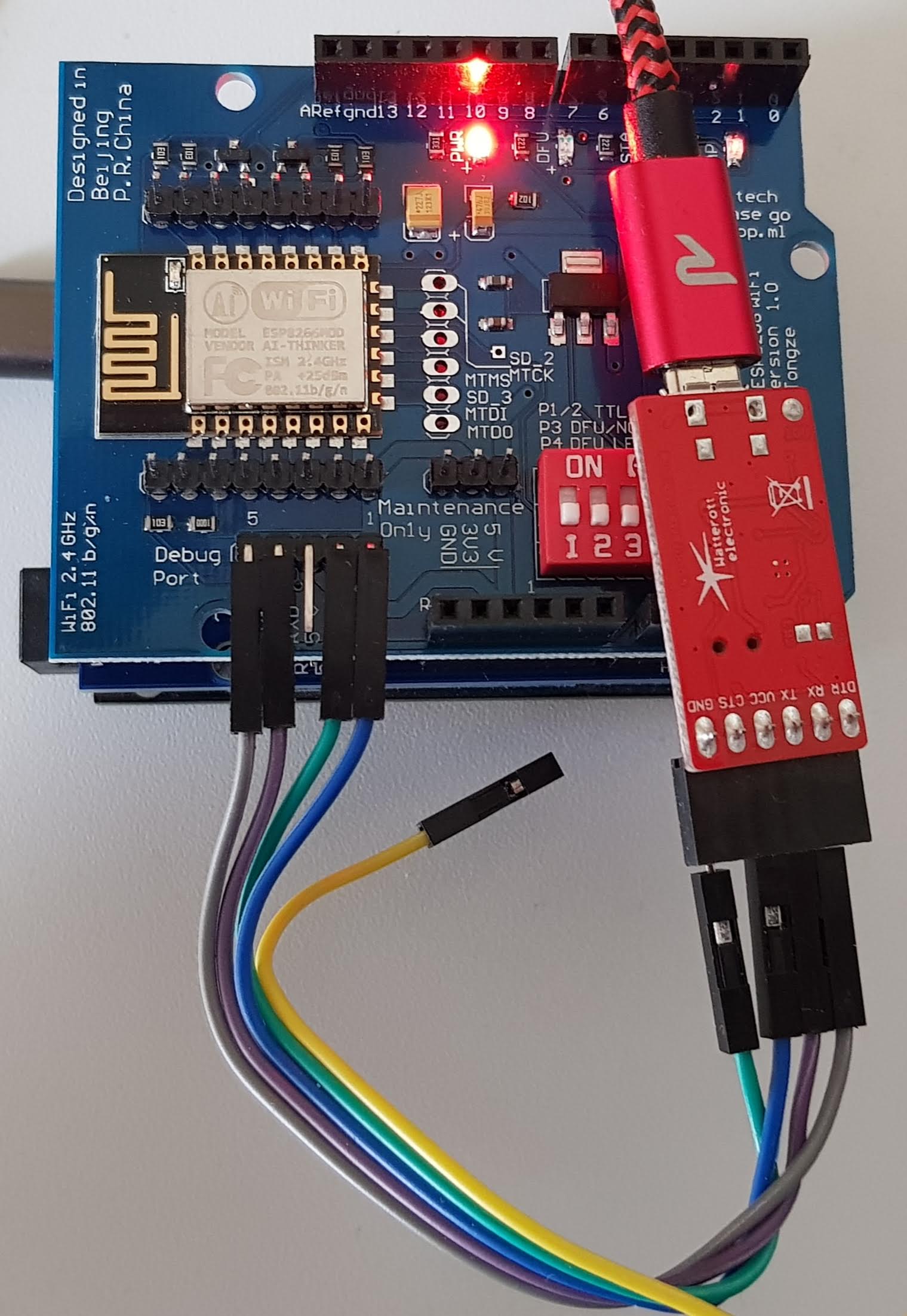
Um die Firmware herauszufinden, habe ich einen Serial zu USB Adapter an den Debugging-Port gehängt. Den Adapter habe ich von 5V auf 3V umgestellt. ACHTUNG – das Board selbst muss noch mit 5V versorgt werden, hierfür habe ich es auf einen Uno gesteckt und diesen ebenfalls an den USB Port gehängt.
Occupancy
| Serial – Adapter | Debug Port ESP |
| Ground | Ground |
| CTS | – |
| VCC | 3V |
| TX | RX |
| RX | TX |
| DTR | – |
This is what it looks like
Console output
Arduino Gui auf den richtigen COM Port einstellen, nach Öffnen der Konsole die Baud-Rate auf 115200 stellen und dann einmal Reset drücken.
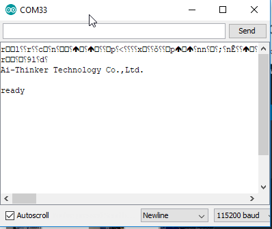
Es handelt sich also um eine AI-Thinker Firmware, hierzu habe ich dann mal Google bemüht, folgende Seiten haben mir beim Verständnis geholfen.
https://www.electrodragon.com/w/ESP8266_AT-Command_firmwareLink status: OK
https://wiki.ai-thinker.com/_media/esp8266/esp8266_series_modules_user_manual_v1.1.pdfLink status: Broken
Es handelt sich somit um eine Firmware, die mit AT Kommandos, wie die alten Modems, gesteuert wird. Dann lesen wir mal die Version aus, hierzu in der Konsole den folgenden Befehl eingeben:
AT+GMRBei mir kam bei allen Befehlen nur ERROR. Ich dachte vielleicht liegts ja am Board, somit mal ein zweites Board probiert. Genau das gleiche Problem. In Foren bin ich auf den Zeilenumbruch gekommen und habe diesen in der Konsole auf New Line + Carriage Return umgestellt. Danach ging es.
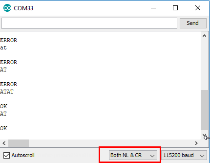
This way, the version can also be read out:
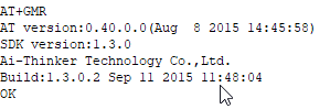
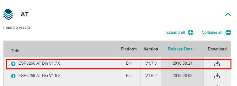
Diese ist nicht gerade die neuste, deshalb erstmal updaten. Die aktuelle Version für die AT Firmware kann bei Espressif, dem Hersteller des ESP, heruntergeladen werden.
https://www.espressif.com/en/products/hardware/esp8266ex/resourcesLink status: OK
Ich nehme für die aktuelle Version 1.6.2 (1.7 ging bei mir nicht) und schaue mal, wie weit ich komme (Direct linkLink status: OK).
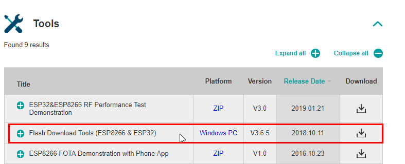
Ein passendes Flash Tool, um die Firmware auf den ESP zu schreiben, gibt es auch gleich bei Espressif (Direct linkLink status: Broken).
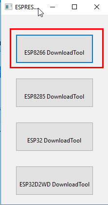
Beim Starten wird gefragt, welcher Chip denn programmiert werden soll, ich wähle den ESP8266.
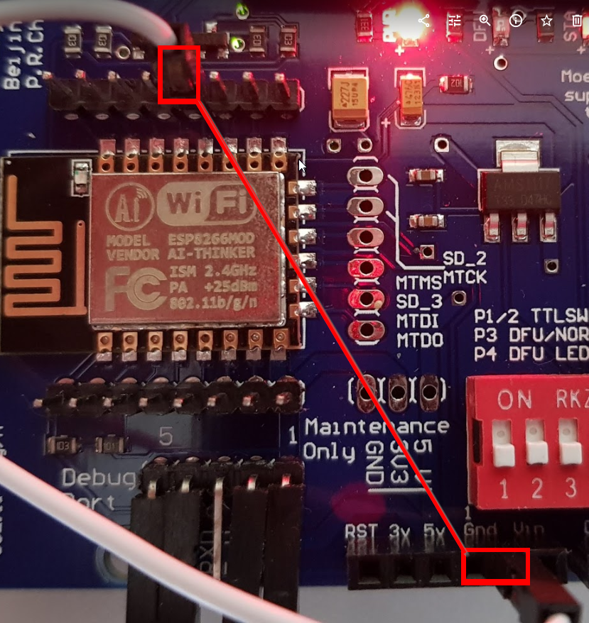
Erst den ESP vorbereiten. Zum Ändern der Firmware muss der GPIO 0 mit Masse verbunden werden. Dies kann über den Dipschalter 3 (auf An) geschehen oder über eine Brücke. Nach dem Programmieren die Verbindung wieder trennen.
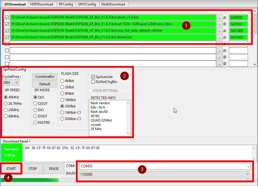
Jetzt ist etwas Fleiß gefragt:
- Entsprechende Dateien und die Speicherstelle, an die sie geschrieben werden sollen, angeben.
- Check settings for your own ESP, please use the settings in the image and adapt them for other ESPs.
- Select COM port and speed
- Start programming.
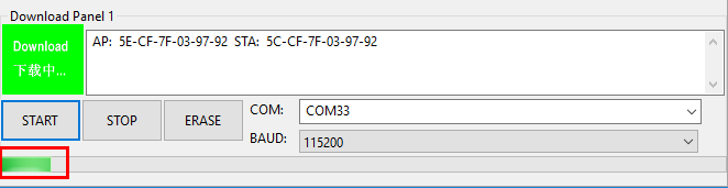
Gibt es keinen Fortschritt? Einfach mal den Press ESP reset, then it should work.
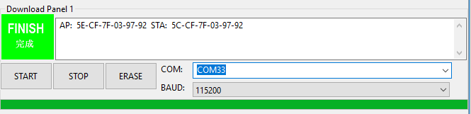
Mal schauen, was die Konsole so hergibt.
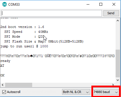
ACHTUNG – Die ersten Zeichen des Controllers werden mit 74880 Baud ausgegeben, deswegen steht da nur Schrummel. Danach geht es mit 115200 weiter. Please set the console to 115200.
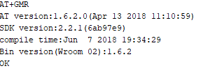
Und siehe da, der AT+GMR Befehl belegt den Erfolg des Flashens.
Communication between ESP and Arduino
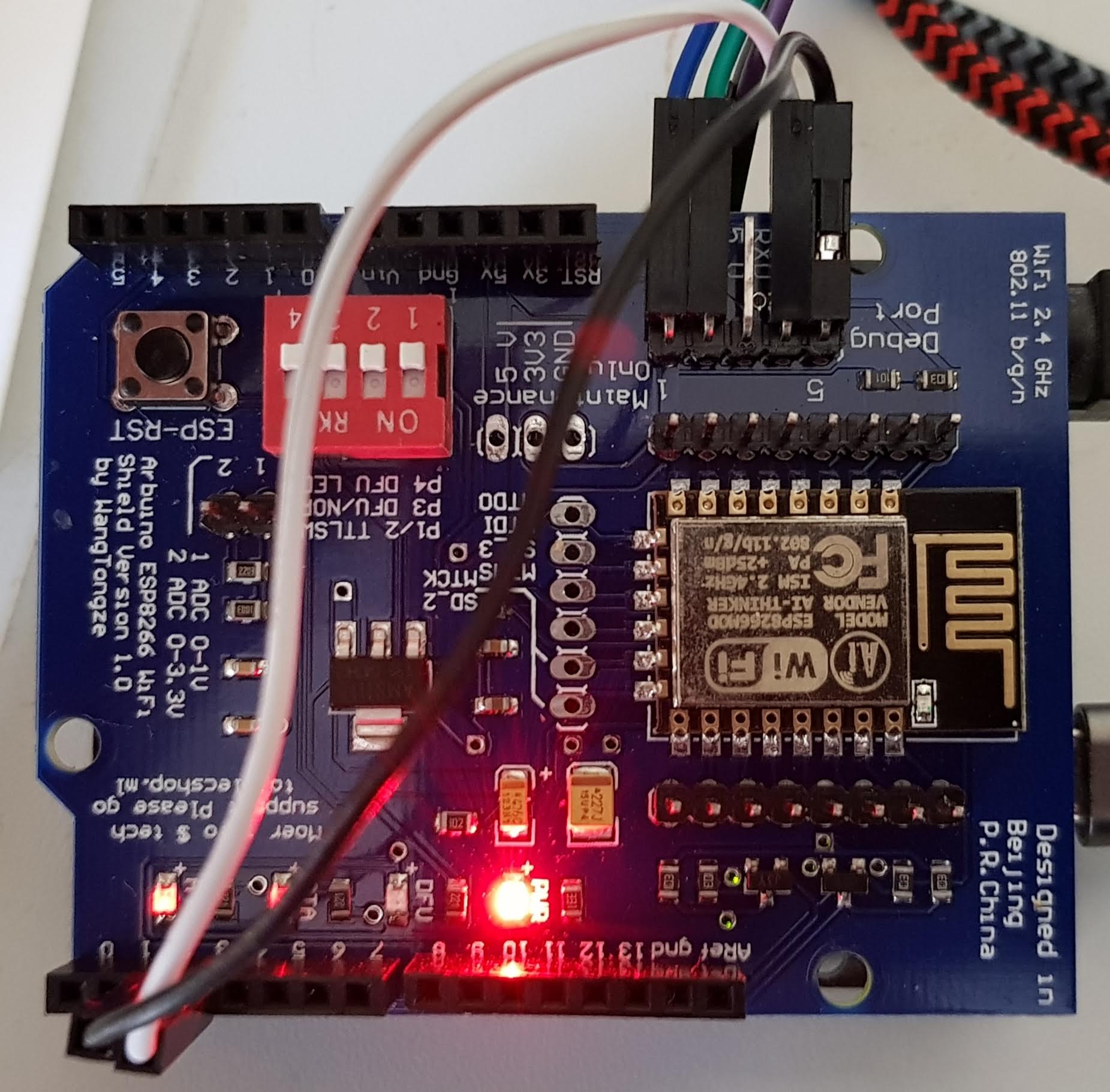
Mit Aktivierung des DIP-Schalters 1 und 2 soll die serielle Schnittstelle des Arduino mit der des ESP verbunden werden. Das klappt leider bei mir nicht. Selbst wenn die Schalter aus sind, lässt sich der Arduino Uno, auf dem die Platine steckt, nicht programmieren. Deshalb gehe ich einen anderen Weg. Ich verbinde den RX/TX Anschluss des ESP mit Pin 2/3 des Unos:
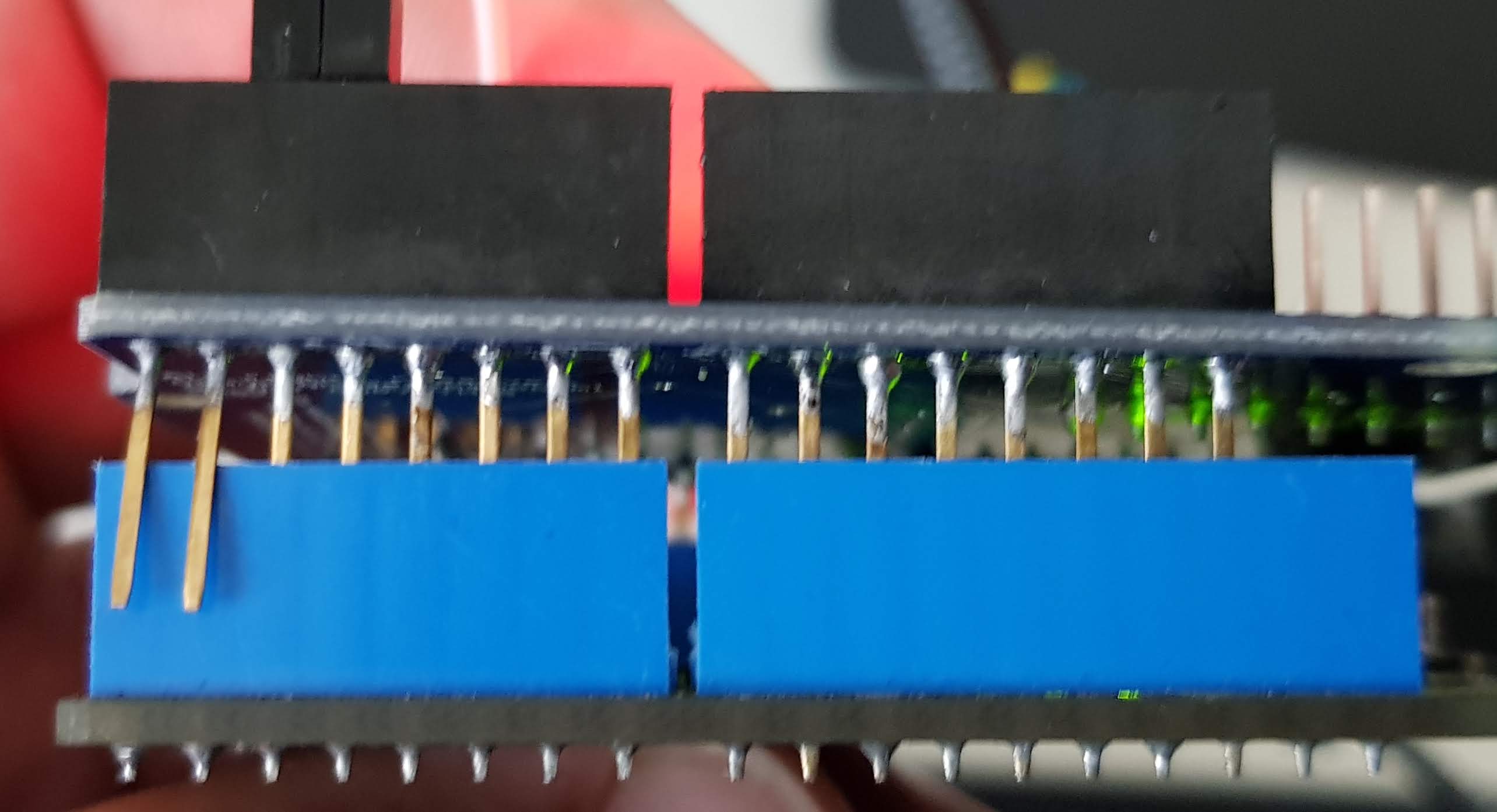
I'm cutting the actual connection:
Ich habe ein kleines Testprogramm geschrieben, welches den Befehl „AT“ über den SoftwareSerial des Arduino an den ESP sendet. Hierbei ist mir aufgefallen, dass es ab und an zu Problemen in der Verbindung kommt. Deshalb habe ich zusätzlich die Übertragungsrate des seriellen Ports per Code auf 9600 heruntergesetzt. Danach konnte ich keine Fehler mehr feststellen.
Die Einstellung ist nur temporär. Sollte die Kommunikation nicht funktionieren, einfach mal den ESP und etwas später den Arduino zurücksetzen. Hier das Programm zum Download:
Programming
Libraries
https://github.com/bportaluri/WiFiEspLink status: OK
Die Bibliothek habe ich dieses Mal per Lib Manager installiert, weil das alleinige Kopieren in den Projektordner zu Compiler Fehlern geführt hat, die ich nicht beheben konnte.
The integration of libraries in general is described under the following link, and I will not go into further detail here.
https://fambach.net/arduino-ide#BibliothekenLink status: OK
Test programme
Als Testbeispiel habe ich mir das UdpNTPClient Beispiel genommen. Vorab habe ich die serielle Schnittstelle des ESP permanent auf 9600 Baud gestellt. (Der Code hierzu befindet sich noch in der Setup Funktion)
Als NTP Zeitserver habe ich meine Fritzbox verwendet, da der Server aus dem Beispiel nicht geantwortet hat. Stellt hier euren Internet Router ein oder einen der freien NTP Server aus dem folgenden Link.
https://www.pool.ntp.org/de/zone/deLink status: OK
Hier nun noch das Beispiel zum Downloaden:
Conclusion
Die Zusatzplatine lässt sich nutzen, hat jedoch ihre Tücken. Gerade wenn es sich um die Nachbau-China-Platine handelt, gilt es ein paar Schritte zu beachten. (Das Plagiat erkennt man an der Aufschrift „Moer info $ tech“.) Es gibt ein paar Tipps und Kniffe im Internet, wie sie dennoch verwendet werden kann. Ich hoffe, ich konnte hier eine gute Möglichkeit, ohne zu löten, zeigen.
Die Platine selbst ist sehr günstig und bietet dem Arduino eine WLAN Verbindung an.
Related Posts
- Arduino VENTUNO QLink status: OK
- Arduino UNO QLink status: OK
- Digispark Rev.3 rettenLink status: OK
- Retro Projekt – FDC USB Floppy Disk ControllerLink status: OK
- Arduino Nano 33 BLELink status: OK
- Arduino Nano 33 IoTLink status: OK
- Preview – Arduino Motor Shield mit L298PLink status: OK
- Preview – Arduino Mega Logger ShieldLink status: OK
- Preview – Prototyp Schild für Arduino Mega Link status: OK
- Preview – Arduino Nano ZusatzplatineLink status: OK
Sources
http://www.rainer-rebhan.de/proj_esp8266.htmlLink status: OK
https://www.clicks-and-stones.de/2017/11/17/esp-12e-wlan-shield-auf-dem-arduino-uno/Link status: Broken
https://www.espruino.com/arduino-esp8266Link status: OK
https://arduino.stackexchange.com/questions/24919/how-to-connect-wi-fi-shield-esp-12e-esp8266-uart-wifi-wireless-shield-with-arduiLink status: Unknown
https://blog.uni-koeln.de/rrzk-knowhow/2017/11/17/esp-12e-wlan-shield-auf-dem-arduino-uno/Link status: Unknown
https://github.com/bportaluri/WiFiEspLink status: OK
https://www.electronicshub.org/update-flash-esp8266-firmware/Link status: Unknown
https://www.espressif.com/en/products/hardware/esp8266ex/resourcesLink status: OK
https://www.az-delivery.de/blogs/azdelivery-blog-fur-arduino-und-raspberry-pi/firmware-flashen-esp8622-01s?ls=de&cache=falseLink status: Unknown
https://arduino.stackexchange.com/questions/24919/how-to-connect-wi-fi-shield-esp-12e-esp8266-uart-wifi-wireless-shield-with-arduiLink status: Unknown
http://stefanfrings.de/esp8266/Link status: Unknown
| Date | Change | Author |
|---|---|---|
| 03.10.2026 | Rechtschreibung korrigiert: Tippfehler, Kommas, Grammatik, Groß-/Kleinschreibung Log-Liste eingefügt | Suffocation |
| 09.11.2016 | Post created | Suffocation |
The Wi-Fi sheet is quite tricky. But with the help of this guide, I managed to get the sheet working. Flashing didn't work for me. Nevertheless, I'm getting the time from the timeserver. Here are a few hints where my attempts failed:
– These instructions refer to the Chinese knock-off. You can recognise the knock-off by the inscription „Moer info $ tech“. (With the knock-off, many of the tips found online are not applicable!)
You must adhere exactly to these instructions, and the plagiarism will work without soldering! This means no switch on ON, do not plug TX/RX into the Arduino Uno as shown, and an external serial connection between Arduino ports 2/3 to the TX/RX of the debug interface.
I couldn't find a terminal program that works at 115200 baud. Only the terminal from the Arduino IDE can handle it, and changing the line ending to \n\r in the Arduino terminal program caused the modem to respond with OK. However, flashing still didn't work. But Wi-Fi works for me even without flashing.
Conclusion: Great post!
Hello Ludger,
Thank you for your comment. Putty I have already used this under Windows/Linux with 115200 baud, possibly the line breaks still need to be configured. Why the programming doesn't work is a mystery to me, but if it works without flashing, it's not absolutely necessary. Are you using the ESP/Arduino for your railway, a truly impressive layout. I am always interested in finding application examples for Arduinos and their ilk.
Hello
Stefan