Last Updated on 25 July 2024 by Suffocation
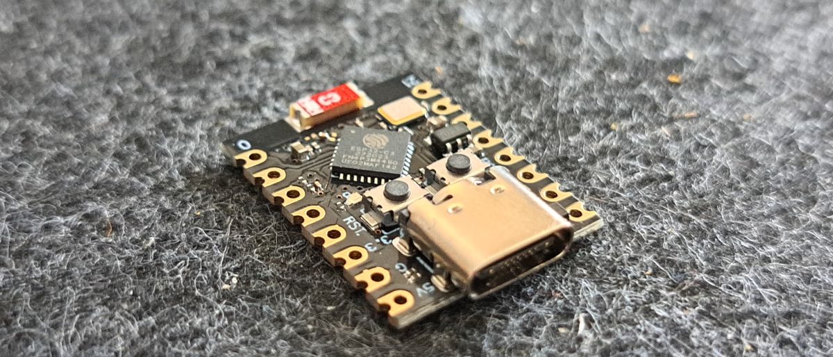
A small ESP32 C3 board for the price in 04/2024 of around ~€3 without shipping. The board should be sufficient for smaller projects, but it offers many advantages of the ESP32 such as WLAN and Bluetooth.
Facts
| Description | Worth |
|---|---|
| Processor | ESP32-C3 Risc-V |
| Wi-Fi | 802.11 b/g/n 2.4Ghz |
| Bluetooth | 5.0 |
| DeepSleep power consumption | 43 µA |
| SRAM | 400KB |
| FLASH | 4 Megabytes |
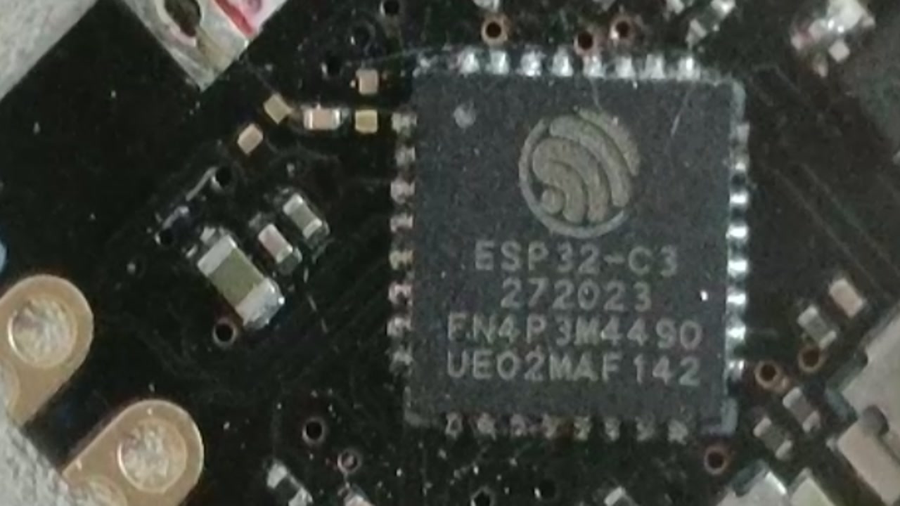
| Chip Model | ESP32C3FN4 |
| External view of ADC | 4 |
| Externally accessible GPIOs | 11 |
| Blue LED | GPIO 8 |
| Dimension | 18mm x 22.5mm |
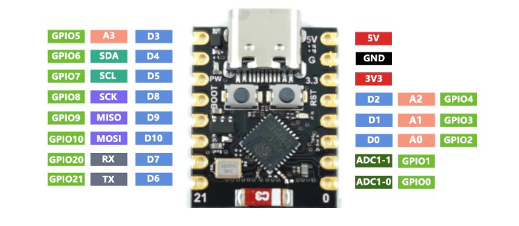
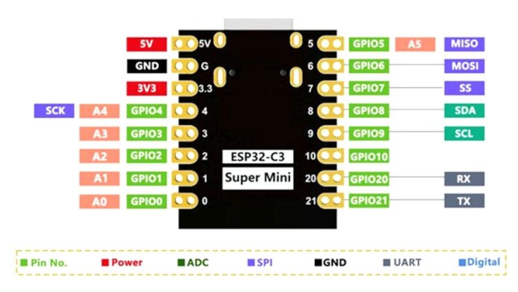
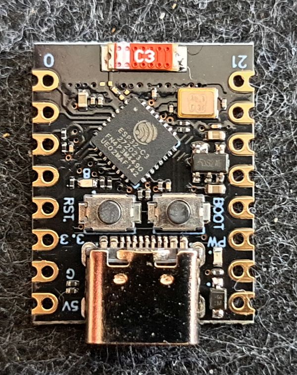
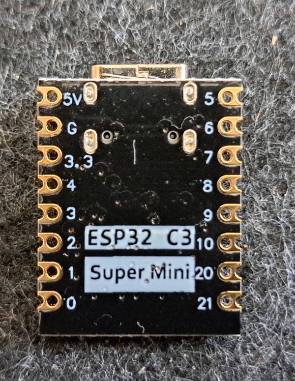
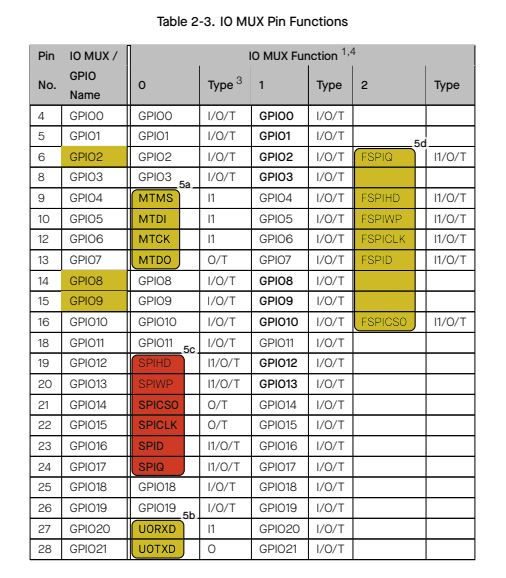
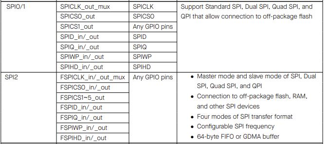
Addendum 25.07.2024: The pinouts on the back differ slightly from the front. Firstly, due to the ADC naming, and secondly, due to the SPI. For SPI on GPIOs 4-7, SPI0/1 is meant. SPI2 is intended to be operated on GPIOs 8-10, whereby its pin allocation can be freely chosen across all GPIOs.
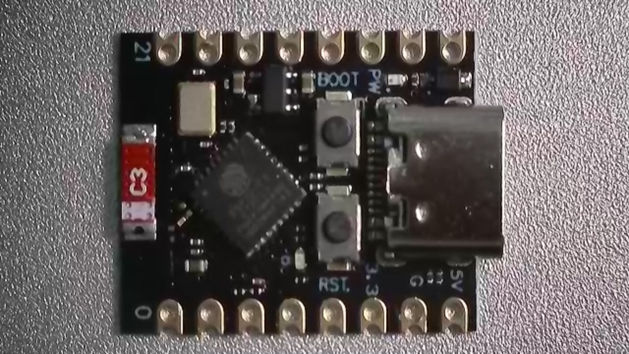
Views
Programming
ESP32 Boardsupport must be installed. (See HERE)
Miscellaneous
No soldered pins
I ordered the version without soldered pins, so I can solder connections directly to the ESP. Anyone who doesn't like soldering should order one of the versions where the pins are already attached.
Pin Multiplexer Assignment
SPI Pinout
Conclusion
USB C, nice and small, what more do you need? A question Seeed Studio also asked themselves, and they've brought an improved version to market (ESP32-C3 Seed Studio Xiao).
Related Posts
- ESP32-C3 Seeed Studio XIAO
- Preview – LuatOS ESP32-C3 Board
- ESP32 Bluetooth Gamepad
- ESP8266/32 WiFi Manager.
- Preview – ESP32 IO Shield for Arduino ESP32 Wroom Core Board
- Preview – ESP-WROOM-32 Rev1 Breadboard Adapter Board
- Preview – 7x9CM Prototyping Soldering Board for ESP8266, ESP-12E, ESP-12F, ESP32
- Preview – ESP32-Audio-Kit ESP32
- LilyGo T-Beam
- TTGO LORA32 OLED V1
Sources
Arduino Forum Entry on the Topic
LOG
| Date | Description |
|---|---|
| 06.04.2024 | Post created |
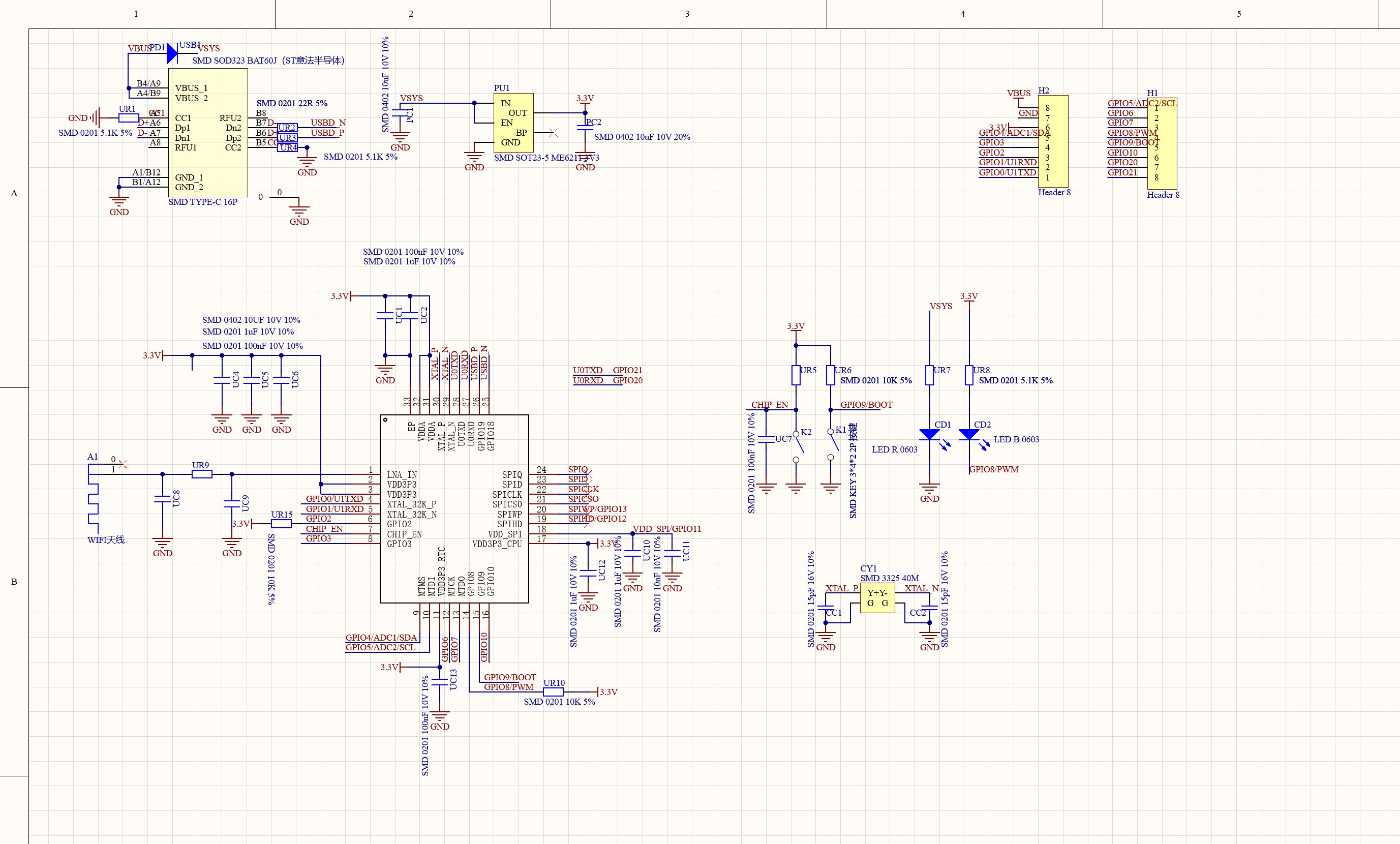
| 25.07.2024 | Following a request from Hans Herzig, SPI information and a datasheet have been added to clarify the SPI assignments on the board. |
There are variants with an I-PEX/U.FL connector for an external antenna. On some of them, it may be necessary to resolder a jumper on the board between the internal and external antenna.
There are also nice little breakout boards.
Hello, is it possible to set Arduino digital outputs GPIO 0 – 4 as open-collector using the Arduino IDE? How? And GPIO 5 as a digital input with pull-up?
Thanks for your help. .
Hello JoKa,
Open collector, in the sense of a higher input voltage, shouldn't work. Connecting multiple outputs together (bus) might be possible as these are protected by diodes. However, I don't have any knowledge about that. Digital output with pull-up:
When initialising:
pinMode(BUTTON_PIN, INPUT_PULLUP);
Take a look here too https://roboticsbackend.com/arduino-input_pullup-pinmode/
Greetings Stefan
Good evening,
On many websites, I find the pinout for the ESP32-C3 Super Mini, both from the top and bottom sides. What I've noticed is,
that MISO, MOSI, SCK in particular are not on the same pins. Why this difference? Can someone explain this to me? In my application (assignment according to the top side) everything works fine.
Thank you for your „enlightenment“
Kind regards
Hans Herzig
Hello Hans,
I think you mean the SPI interface when you write MOSI, MISO, SCK. The C3 has a total of 3 SPI interfaces. 0/1 are intended for the flash memory and are routed out to GPI 4-7. According to the datasheet, SPI 2 can be operated on any GPIO pin. I have added the corresponding pictures and datasheets to the post. However, it is still unclear to me why the analogue inputs are named differently and not according to the ADC1/2 and the port. I hope this helps. Regards Stefan
Has anyone ever done/seen an SPI project with clear SPI wiring? The confusion with the pins is perfect. Which pins/GPIOs are wired how to correctly wire, for example, a C1101 from the ESP32C3 SUPER MINI. Many thanks for any feedback, Gilli