Last Updated on 18. October 2026 by SuffocationLink status: OK
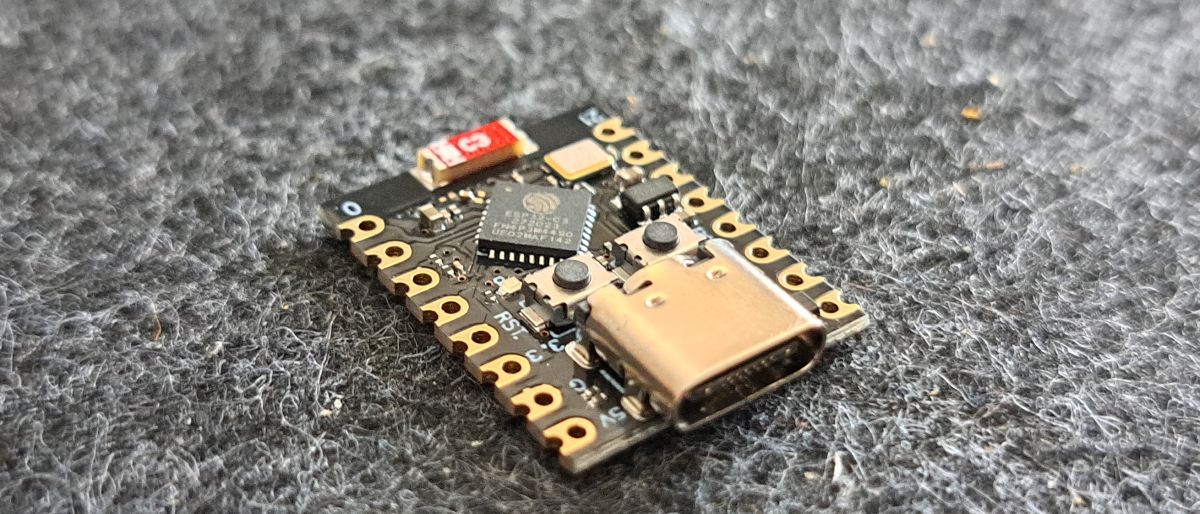
Ein kleines ESP32 C3 Board zum Preis 04/2024 von rund ~3€ ohne Versand. Für kleinere Projekte sollte das Board ausreichend sein, es bietet jedoch viele Vorteile des ESP32 wie WLAN und BlueTooth.
Facts
| ESP32-C3 Super Mini | |
|---|---|
| Processor | ESP32-C3 (RISC-V, 32 Bit), ESP32-C3FN4 |
| Kernel | 1 |
| Tact | 160 MHz |
| Flash | 4 MB |
| SRAM | 400 KB |
| Digitale Pins | 11 |
| Analoge Eingänge | 4 |
| UART | 2 |
| I²C | 1 |
| WLAN | 802.11 b/g/n, 2,4 GHz |
| Bluetooth | Bluetooth LE 5.0 |
| USB | USB-C |
| Input voltage | 5 V (USB-C) oder 3,3–6 V (5-V-Pin) |
| Stromaufnahme | 43 µA (Deep Sleep) |
| Abmessungen | 18 × 22,5 mm |
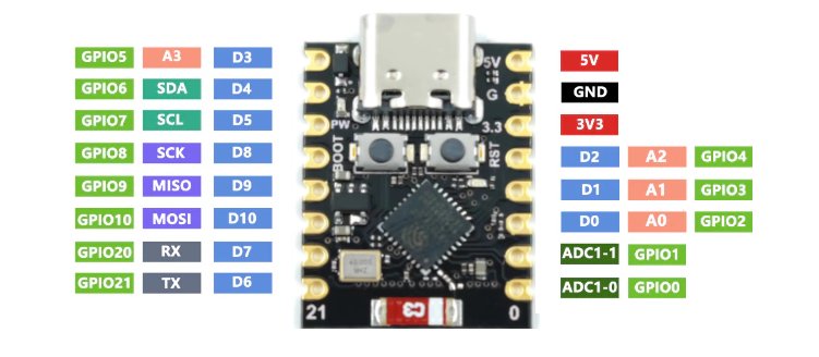
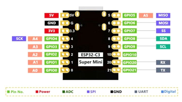
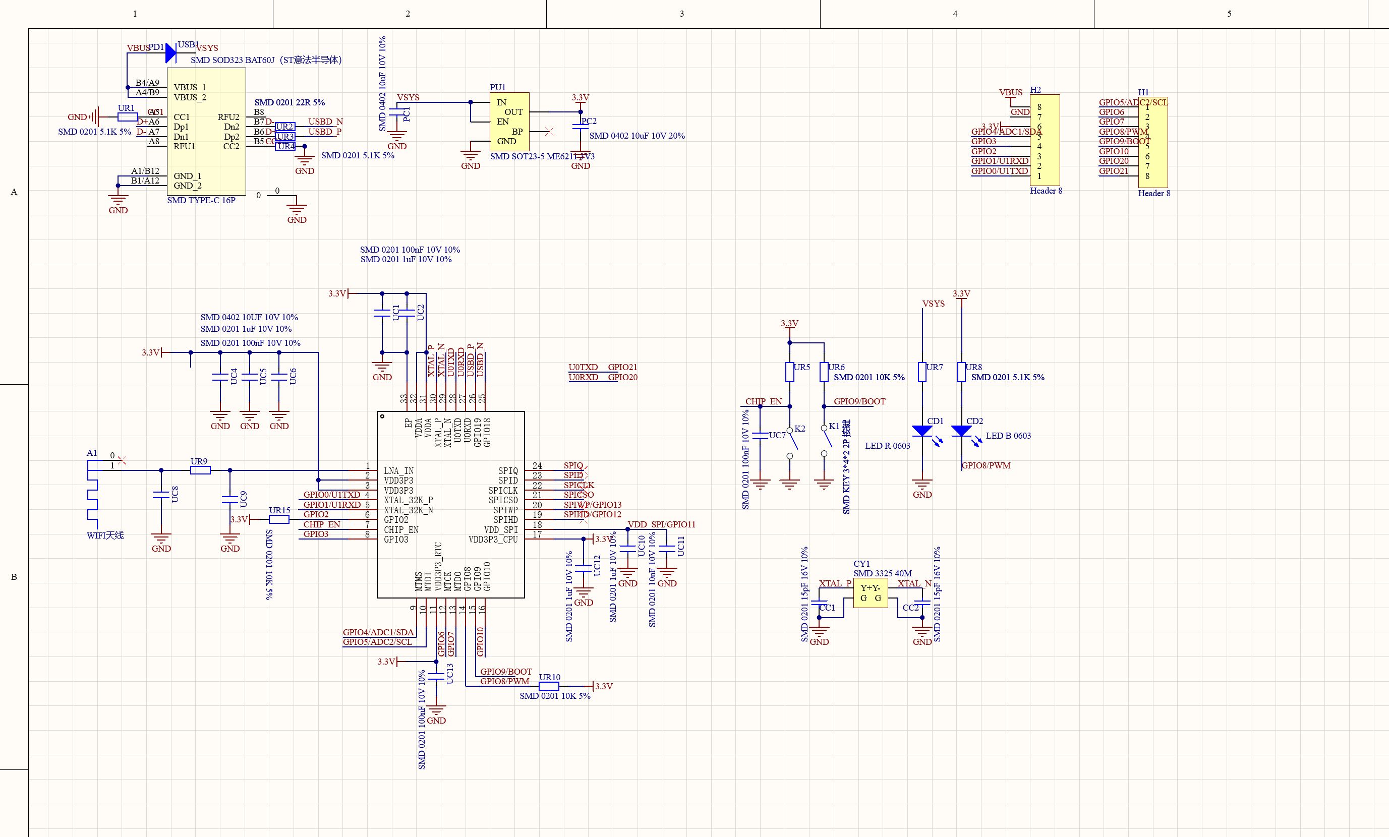
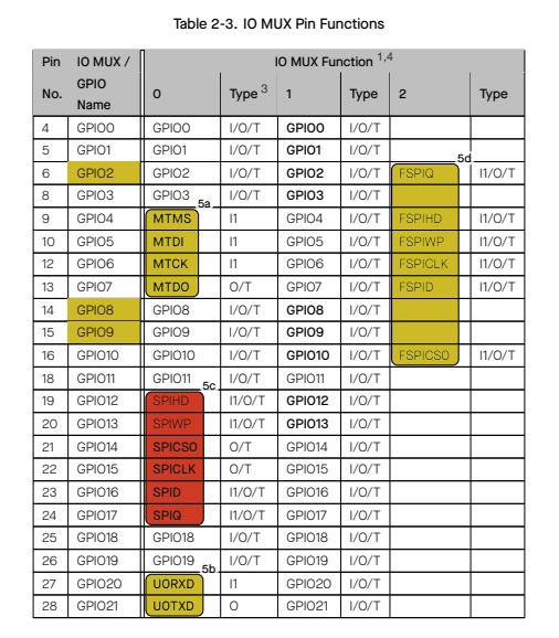
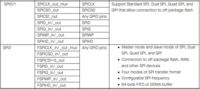
Nachtrag 25.07.2024: Pinout der Rückseite unterscheidet sich ein wenig zur Vorderseite. Zum einen durch die ADC Benennung, zum anderen durch die SPI. Beim SPI an GPIO 4-7 ist SPI0/1 gemeint. An GPIO 8-10 soll der SPI2 betrieben werden, wobei dieser in seiner Pinbelegung frei über alle GPIOs wählbar ist.
Views
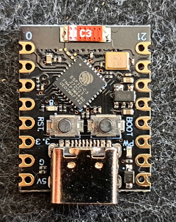
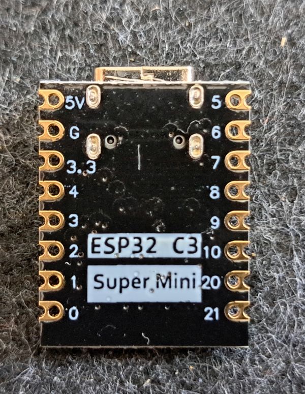
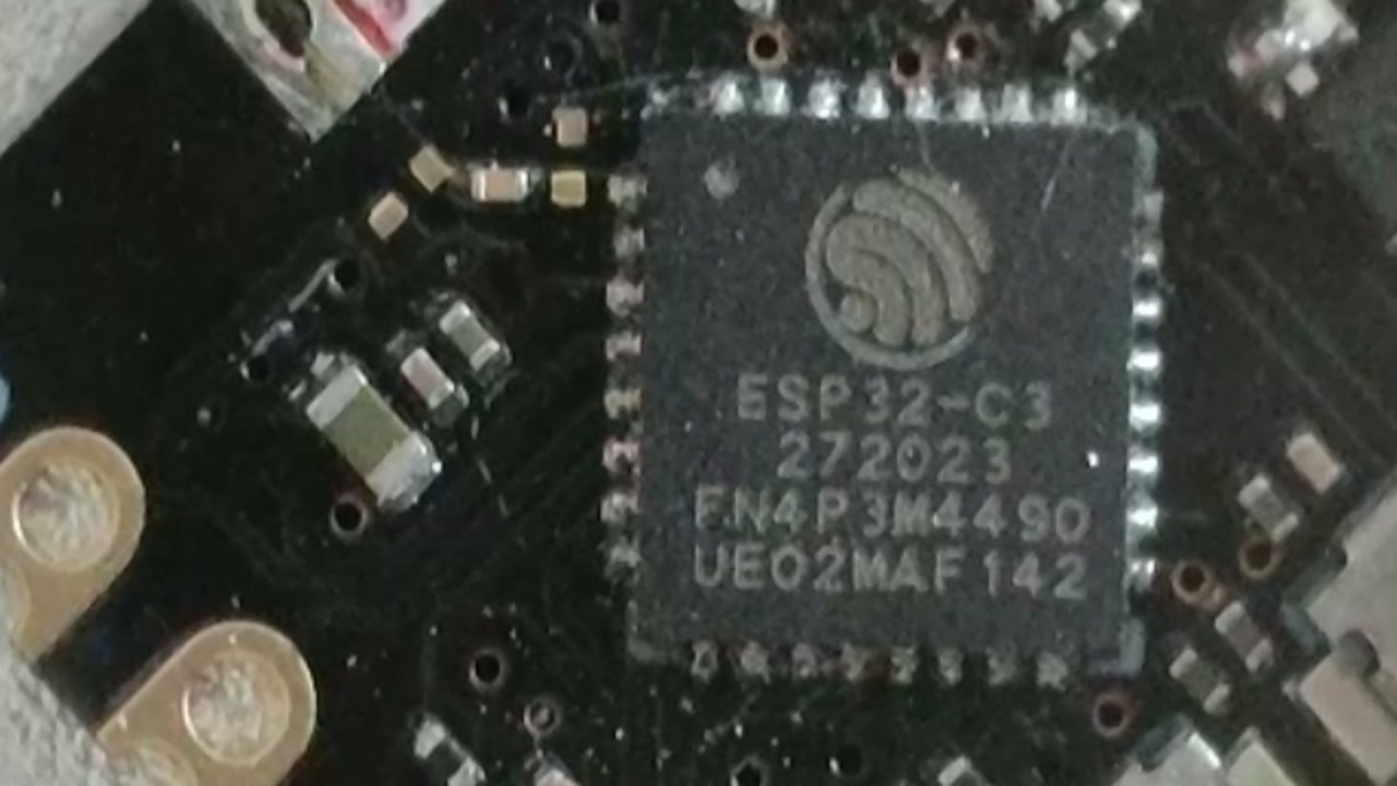
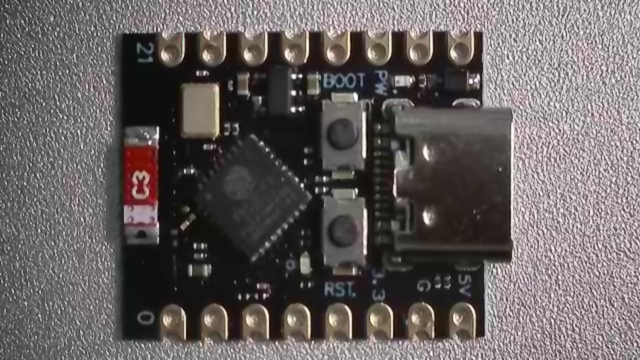
Programming
ESP32 Boardsupport must be installed. (See HERELink status: OK)
Miscellaneous
No soldered pins
Ich habe die Version ohne verlötete Pins bestellt, um Verbindungen direkt an den ESP löten zu können. Wer nicht löten mag, sollte eine Version bestellen, bei der die Pins schon befestigt sind.
Pin Multiplexer Assignment
SPI Pinout
Conclusion
USB C, schön klein, was braucht man mehr? Eine Frage, die sich auch Seeed Studio gestellt hat und eine verbesserte Version auf den Markt gebracht hat (ESP32-C3 Seeed Studio XiaoLink status: OK).
Related Posts
- October Check 2026 – Neue Mikrocontroller und BoardsLink status: OK
- Ulanzi TC001 Smart Pixel ClockLink status: OK
- ESP32-C3 Seeed Studio XIAOLink status: OK
- Preview – LuatOs ESP32-C3 BoardLink status: OK
- ESP32 Bluetooth GamepadLink status: OK
- ESP8266/32 WiFi Manager.Link status: OK
- Preview – ESP32-IO Schild für Arduino ESP32 Wroom Core BoardLink status: OK
- Preview – ESP-WROOM-32 Rev1 Steckbrett Adapterplatine Link status: OK
- Preview – 7x9CM Prototyp Platine zum Löten für ESP8266, ESP-12E, ESP-12F, ESP32Link status: OK
- Preview – ESP32-Audio-Kit ESP32Link status: OK
Sources
Searching on AliExpressLink status: OK
Arduino Forum Entry on the TopicLink status: OK
LOG
| Date | Change | Author |
|---|---|---|
| 19.10.2026 | Fakten-Tabelle durch Datenblock aus dem Modell ersetzt | Suffocation |
| 08.10.2026 | Überschriften-Hierarchie korrigiert (H1→H2, Unterebenen eine Stufe tiefer) | Suffocation |
| 04.10.2026 | Rechtschreibung korrigiert: außen, ein wenig, Seeed u. a., Kommasetzung | Suffocation |
| 03.10.2026 | Logbuch-Tabelle auf Log-Liste umgestellt | Suffocation |
| 25.07.2024 | Following a request from Hans Herzig, SPI information and a datasheet have been added to clarify the SPI assignments on the board. | Suffocation |
| 06.04.2024 | Post created | Suffocation |
There are variants with an I-PEX/U.FL connector for an external antenna. On some of them, it may be necessary to resolder a jumper on the board between the internal and external antenna.
There are also nice little breakout boards.
Hello, is it possible to set Arduino digital outputs GPIO 0 – 4 as open-collector using the Arduino IDE? How? And GPIO 5 as a digital input with pull-up?
Thanks for your help. .
Hello JoKa,
Open collector, in the sense of a higher input voltage, shouldn't work. Connecting multiple outputs together (bus) might be possible as these are protected by diodes. However, I don't have any knowledge about that. Digital output with pull-up:
When initialising:
pinMode(BUTTON_PIN, INPUT_PULLUP);
Take a look here too https://roboticsbackend.com/arduino-input_pullup-pinmode/
Greetings Stefan
Output als open-Collector einstellen – NEIN.
Digital-Input mit (intern) Pullup – JA
Hinweis: Ein Blick in die Spezifikation verrät, dass die GPIO Pins – im Gegensatz zur häufig vertetenen Auffassung – NICHT „fehlertolerant“ sind und durch Anlegen von höherer Spannung als der Versorgungsspannung des Chips beschädigt, bzw. zerstört werden können. Die integrierten Schutzdioden könnte man prinzipiell dafür verwenden, aber nur, dann wenn man den Strom entsprechend begrenzt. Ist aber wegen zusätzlicher Verlustleistung und Störeinflüssen nicht empfehlenswert. Abgesehen davon kosten LevelShifter boards eh so gut wie nix.
Good evening,
On many websites, I find the pinout for the ESP32-C3 Super Mini, both from the top and bottom sides. What I've noticed is,
that MISO, MOSI, SCK in particular are not on the same pins. Why this difference? Can someone explain this to me? In my application (assignment according to the top side) everything works fine.
Thank you for your „enlightenment“
Kind regards
Hans Herzig
Hello Hans,
I think you mean the SPI interface when you write MOSI, MISO, SCK. The C3 has a total of 3 SPI interfaces. 0/1 are intended for the flash memory and are routed out to GPI 4-7. According to the datasheet, SPI 2 can be operated on any GPIO pin. I have added the corresponding pictures and datasheets to the post. However, it is still unclear to me why the analogue inputs are named differently and not according to the ADC1/2 and the port. I hope this helps. Regards Stefan
Has anyone ever done/seen an SPI project with clear SPI wiring? The confusion with the pins is perfect. Which pins/GPIOs are wired how to correctly wire, for example, a C1101 from the ESP32C3 SUPER MINI. Many thanks for any feedback, Gilli
läuft seit fast 3 Jahren ohne Probleme
c3-sm – ips tft (ST7789)
MISO D5 – n.a.
MOSI D6 – SDA
CS D7 – CS
RST D9 – RES
DC D10 – DC
SCLK D4 – SCL
BL D21 – BLK