Last Updated on 15. October 2026 by SuffocationLink status: OK
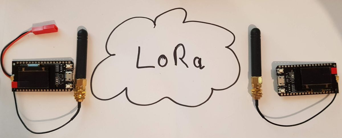
Ich habe diese LoRa-Boards vor einiger Zeit im Doppelpack erworben und in der Schublade vergessen. Da nun immer mehr Berichte zum Thema LoRa (Long Range Radio) zu finden sind, wollte ich es auch mal ausprobieren. Meine Versuche habe ich hier dokumentiert.
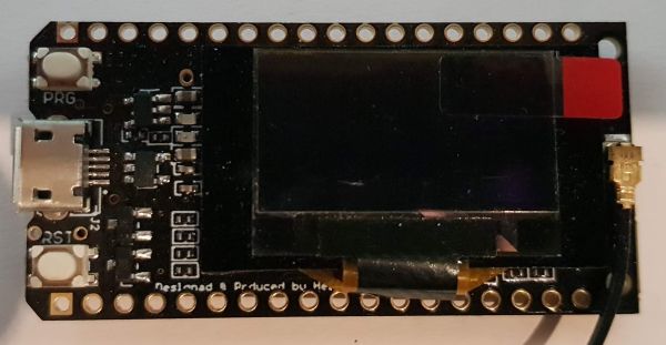
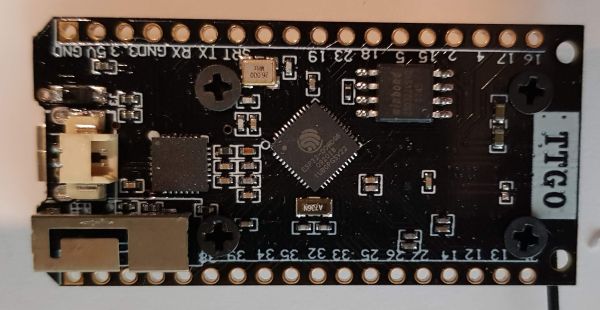
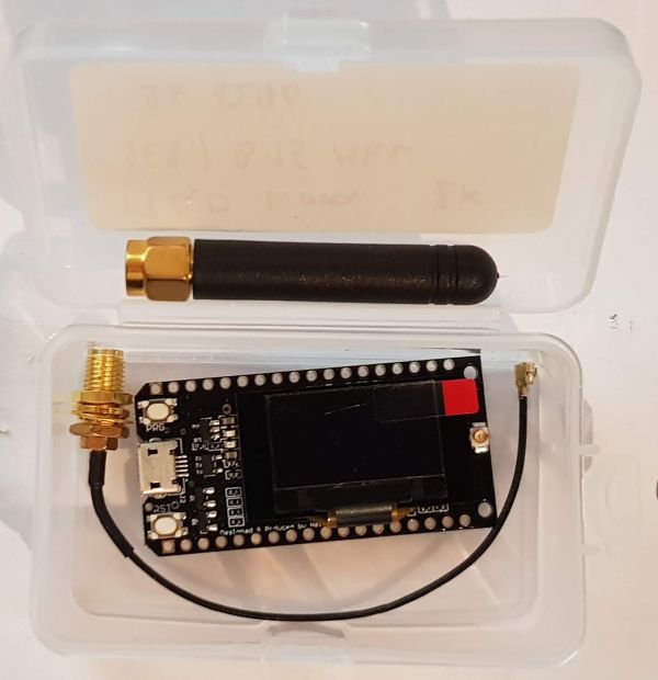
Es gibt mittlerweile eine Version 2 des Boards. Die Version 2 hat zusätzlich einen AN-Schalter. Hieran kann man die beiden Versionen ganz gut unterscheiden.
Facts
- ESP32
- Display SSD1306
- LoRa Chip SX1276
- 2 Taster – Reset und Prog
- Antenna connection for LoRa antennas
- Just 2x 1.5 mm Lipo connector
- Charging LED red.
- Micro USB CP2100x
- Metal antenna for WiFi
- Fits on breadboard (1 row free on each side)
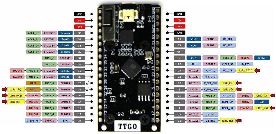
SX1276 LoRa Chip
| Spanish | SX1276 |
| GPIO 19 | Miso |
| GPIO 27 | MOSI |
| GPIO 5 | SCK |
| GPIO 18 | Computer Science |
| GPIO 26 | IRQ |
| GPIO 14 | RST |
SSD1306 OLED Display
The I2C address is 0x3C.
| Spanish | Display |
|---|---|
| GPIO 4 | Seventh-day Adventist |
| GPIO 15 | SCL |
| GPIO 16 | RST |
Areas of application
- Remote maintenance
- Sensor nodes
Views
Programming
Libraries
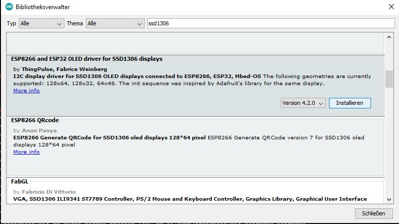
SSD1306
Graphics library
https://github.com/ThingPulse/esp8266-oled-ssd1306Link status: OK
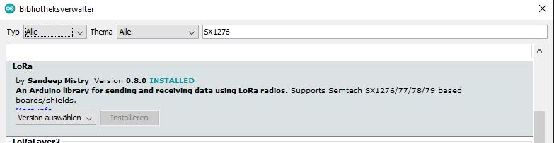
SX1276
Lora by Sandeep Mistry
https://github.com/sandeepmistry/arduino-LoRaLink status: OK
Test programme
TTGO liefert ein paar Beispiele, unter anderem einen Sender und einen Empfänger. Die beiden folgenden Programme sind Modifikationen davon.
Sender
Source code OLED_LoRa_Sender.ino (GitHubLink status: OK)
#include <SPI.h>
#include <LoRa.h>
#include <Wire.h>
#include "SSD1306.h"
#include "images.h"
#include "OledTable.h"

#define SCK     5    // GPIO5  -- SX1278's SCK
#define MISO    19   // GPIO19 -- SX1278's MISO
#define MOSI    27   // GPIO27 -- SX1278's MOSI
#define SS      18   // GPIO18 -- SX1278's CS
#define RST     14   // GPIO14 -- SX1278's RESET
#define DI0     26   // GPIO26 -- SX1278's IRQ(Interrupt Request)
#define BAND    433E6

unsigned int counter = 0;

#define DISPLAY_SDA 4
#define DISPLAY_SCL 15
#define DISPLAY_RST 16
#define SSD_ADDRESS 0x3c

SSD1306 display(SSD_ADDRESS, DISPLAY_SDA, DISPLAY_SCL);
OledTable table(&display,2,2);

String rssi = "--";
String packSize = "--";
String packet ;

int lineCount = 1;
int lineHeight =0;//=  display.getHeight()/lineCount;
int colSize = 0 ; //display.getWidth()/2;


void setup() {

  // Init display
  pinMode(DISPLAY_RST,OUTPUT);
  digitalWrite(DISPLAY_RST, LOW);    // set GPIO16 low to reset OLED
  delay(50);
  digitalWrite(DISPLAY_RST, HIGH); // while OLED is running, must set GPIO16 in high、
  display.init();
  display.flipScreenVertically();
  display.setTextAlignment(TEXT_ALIGN_LEFT);
  display.setFont(ArialMT_Plain_10);

  // init table
  table.init();

  pinMode(25, OUTPUT);
  Serial.begin(9600);
  while (!Serial);
  Serial.println();
  Serial.println("LoRa Sender Test");

  SPI.begin(SCK, MISO, MOSI, SS);
  LoRa.setPins(SS, RST, DI0);
  if (!LoRa.begin(433E6)) {
    Serial.println("Starting LoRa failed!");
    while (1);
  }
  //LoRa.onReceive(cbk);
  //  LoRa.receive();
  Serial.println("init ok");
  delay(1500);
}

void loop() {
  table.clear();
  table.setText(0,0, "Sending packet: ");
  table.setText(0,1, String(counter));
  table.refresh();

  // send packet
  LoRa.beginPacket();
  LoRa.print("hello ");
  LoRa.print(counter);
  LoRa.endPacket();

  counter++;
  digitalWrite(25, HIGH);   // turn the LED on (HIGH is the voltage level)
  delay(1000);                       // wait for a second
  digitalWrite(25, LOW);    // turn the LED off by making the voltage LOW
  delay(1000);                       // wait for a second
}
Recipient
Source code OLED_LoRa_Receiver.ino (GitHubLink status: OK)
/**
* LoRa Receiver
*
* Created by TTGO
* Modified by StefFam https://www.fambach.net
*/

#include "OledTable.h"
#include <SPI.h>
#include <LoRa.h>
#include <Wire.h>
#include <SSD1306.h>
#include "images.h"

#define SCK     5    // GPIO5  -- SX1278's SCK
#define MISO    19   // GPIO19 -- SX1278's MISO
#define MOSI    27   // GPIO27 -- SX1278's MOSI
#define SS      18   // GPIO18 -- SX1278's CS
#define RST     14   // GPIO14 -- SX1278's RESET
#define DI0     26   // GPIO26 -- SX1278's IRQ(Interrupt Request)
#define BAND    433E6

#define DISPLAY_SDA 4
#define DISPLAY_SCL 15
#define DISPLAY_RST 16
#define SSD_ADDRESS 0x3c

SSD1306 display(SSD_ADDRESS, DISPLAY_SDA, DISPLAY_SCL);
OledTable table(&display,3,2);

String rssi = "--";
String packSize = "--";
String packet ;


int lineCount = 5;
int lineHeight =0;//=  display.getHeight()/lineCount;
int colSize = 0 ; //display.getWidth()/2;


void loraData(){

  table.clear();
  table.setText(0,0,"Rssi");
  table.setText(0,1, String(rssi));

  table.setText(1,0 ,"Received ");
  table.setText(1,1 ,String(packSize)+"[bytes]");

  table.setText(2,0 ,"Content");
  table.setText(2,1 ,packet);

  table.refresh();
}

void cbk(int packetSize) {
  packet ="";
  packSize = String(packetSize,DEC);
  for (int i = 0; i < packetSize; i++) { packet += (char) LoRa.read(); }
  rssi = "RSSI " + String(LoRa.packetRssi(), DEC) ;
  loraData();
}

void setup() {

  // Init display
  pinMode(DISPLAY_RST,OUTPUT);
  digitalWrite(DISPLAY_RST, LOW);    // set GPIO16 low to reset OLED
  delay(50);
  digitalWrite(DISPLAY_RST, HIGH); // while OLED is running, must set GPIO16 in high、
  display.init();
  display.flipScreenVertically();
  display.setTextAlignment(TEXT_ALIGN_LEFT);
  display.setFont(ArialMT_Plain_10);

  // init table
  table.init();

  Serial.begin(115200);
  while (!Serial);
  Serial.println();
  Serial.println("LoRa Receiver Callback");
  SPI.begin(SCK,MISO,MOSI,SS);
  LoRa.setPins(SS,RST,DI0);
  if (!LoRa.begin(433E6)) {
    Serial.println("Starting LoRa failed!");
    while (1);
  }
  //LoRa.onReceive(cbk);
  LoRa.receive();
  Serial.println("init ok");

}

void loop() {
  int packetSize = LoRa.parsePacket();
  if (packetSize) { cbk(packetSize);  }
  delay(10);
}
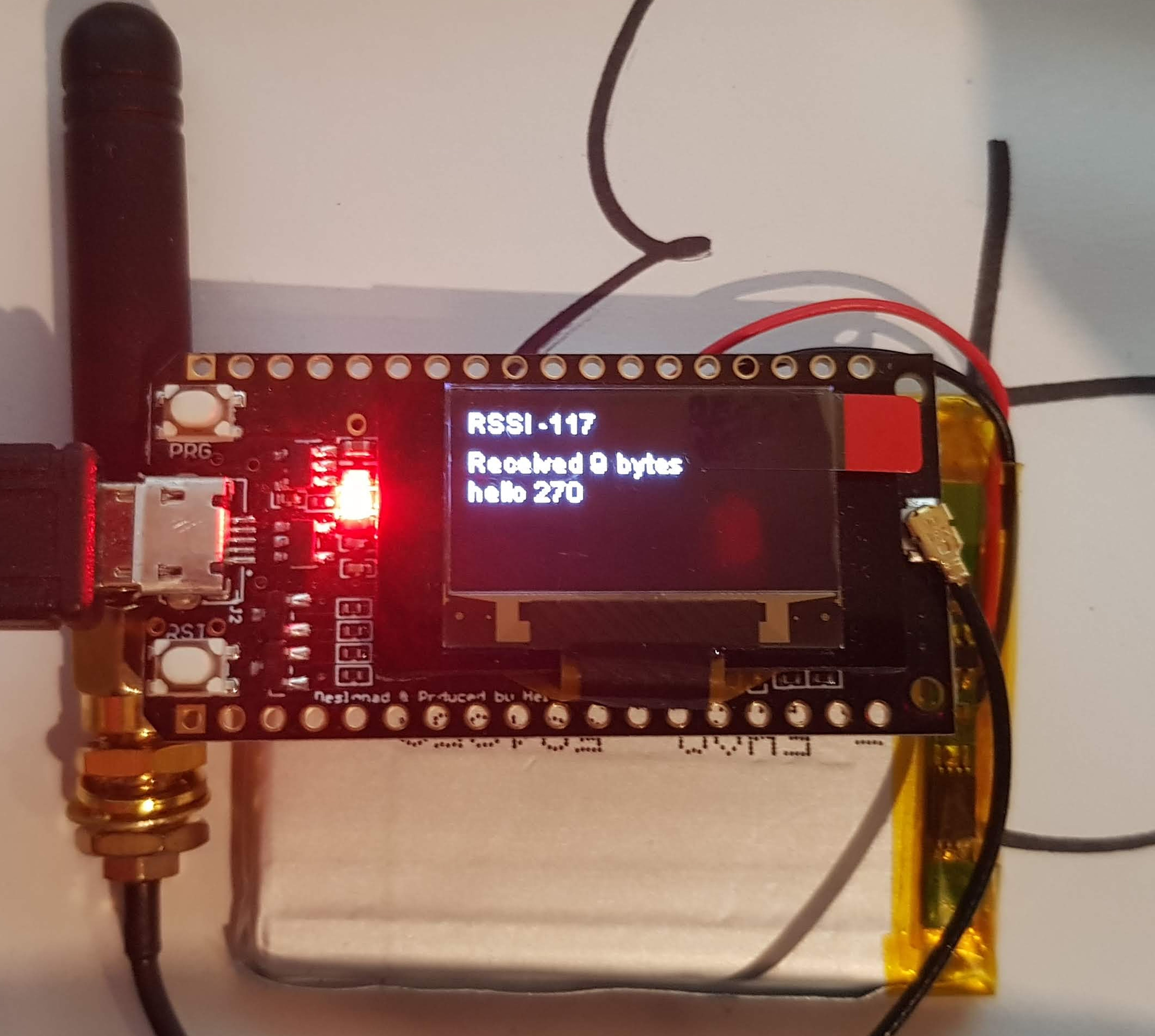
So sieht’s aus
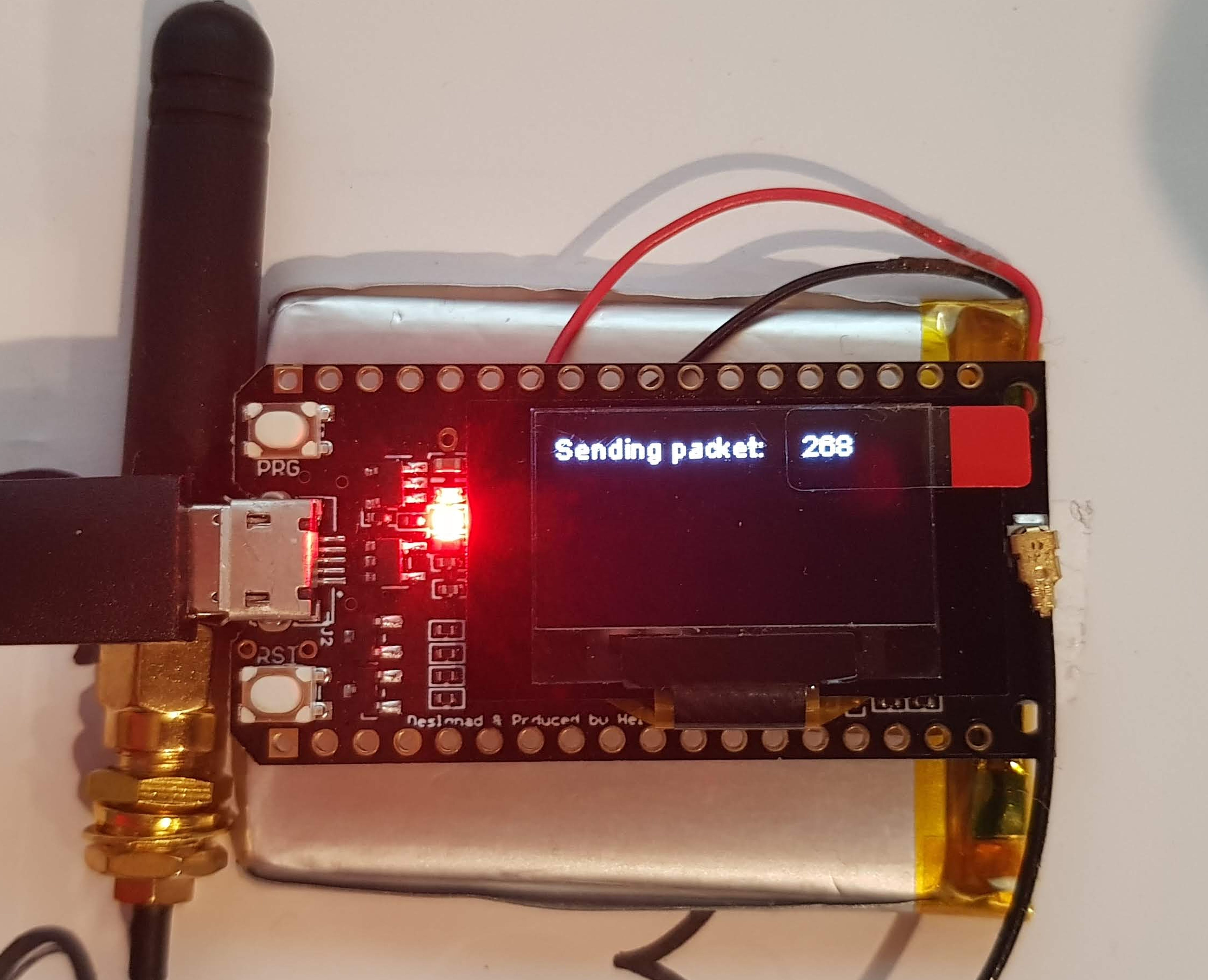
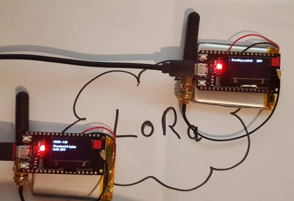
Problems
Currently none
Miscellaneous
…
Conclusion
Ein nettes Einsteigerkit. Die Informationen waren etwas schwer zu finden, aber es gibt andere Seiten als die des Herstellers, die gute Tipps geben. Die Verbindung per LoRa ist problemlos. Tests bezüglich der Reichweite und Stabilität habe ich nicht durchgeführt.
| Date | Change | Author |
|---|---|---|
| 15.10.2026 | „Verwandte Beiträge“ auf Block „UB Mehr zum Thema“ umgestellt, alter Quellen-Listen-Block entfernt (Quellen kommen aus dem Beitrags-Template) Beispielcode Sender/Empfänger als Code-Block eingefügt (Einbettung über gist-it.appspot.com funktionierte nicht mehr) | Suffocation |
| 03.10.2026 | Rechtschreibung korrigiert: Tippfehler, Kommas, Groß-/Kleinschreibung Log-Liste eingefügt | Suffocation |
| 25.01.2021 | Post created | Suffocation |
I can only report good things about the range of the TTGO LoRa V2 boards with 433MHz. At least my boards run in the TinyGS project as LoRa sat trackers, and there I've had confirmed reception contacts with the LoRa sat RS52SE at a distance of 2200km with the supplied rubber duck antenna and indoors. However, the sat had a transmit power of 1W and was heard at RSSI -132dBm with -17.8dB S/N. The various sats are regularly received well at distances of 500 – 1500km.
Information on the project at Tinygs.com.
Hello,
I ordered a LoRa32 board from Dschunke7 (so a return is rather problematic).
Unfortunately, the small OLED display isn't working.
Given that the boards have become extremely expensive in the last quarter, here's my question:
Can the display be easily replaced? Can a larger one be soldered on? Swap the hardware and that's it (plug and play?)?
Best regards
Hello,
I've already swapped displays, so it is possible. You need to make sure the pins are the same and the resolution is correct. I've also soldered on an I2C display where none was previously present; you can then determine the size yourself.
Hello
Stefan
Hello again...
Hoping to increase the range, I bought two new antennas on eBay. The success was non-existent, so I won't even link them here…
Out of boredom, I read this report again and was taken aback: the photos show an RSSI of -117.
At range, it should definitely be more (at -120, it should stop?!) and so I wondered why it still worked and installed the demo cited here. The values were just as awful.
The error was quickly found: the modules are the 868 MHz version. They therefore must be used with
LoRa.begin(868E6)
initiated. And lo and behold, suddenly you have RSSI values of -30 over the short distance.
Sounds good?! But it's still not enough to reach from inside to the door 🙁
If one were to increase the transmission power now
LoRa.setTxPower(20, PA_OUTPUT_PA_BOOST_PIN);
After Lora.Begin
Will the RSSI get any larger?.
Unfortunately, I don't have any measuring equipment (or the know-how) to figure out why the range is so rubbish and whether it's a system error or a problem with my hardware…
Stefan: Perhaps you fancy grabbing a power bank and taking the receiver outside sometime?!
Hello Lars,
I naturally wanted to, but didn't have the time. Today it worked out. After I set up the software for the two nodes, I let my children run around the park with the box. Unfortunately, I don't have such clear line-of-sight here. But I did get over 200m. I switched the frequency to 868. I'm not sure if the chip can do them all (according to the datasheet), but the antenna definitely can't. I ordered a measuring device for antennas but never received it…. . We stopped at around 500 meters. There were some trees in between and no line of sight. Packets were received. Depending on the position, however, there were interferences. Regards Stefan ... More on the project setup may follow 😉
Hello Stefan and fellow readers,
Thank you very much for the effort! You're making me jealous! 500m wasn't possible for me at all, and there wasn't even anything in the way..
I probably need more modules to see if one of mine is faulty, but somehow I've lost the desire for now (?)…
Would you perhaps like to adjust the sketch to the correct frequency?
Best regards,
Lars
I also have the parts (Version 1) lying around. Unfortunately, they were never used because the range between them was something like 200m 🙁 (clear line of sight). That might be enough for one or two applications, but unfortunately not for mine (transmitting a few bytes per day) from a location without internet to a location with internet access. Not to mention, to an access point of „The Things Network“.
I'm currently doing this with GSM and would like to replace it...