Last Updated on 21 June 2026 by Suffocation
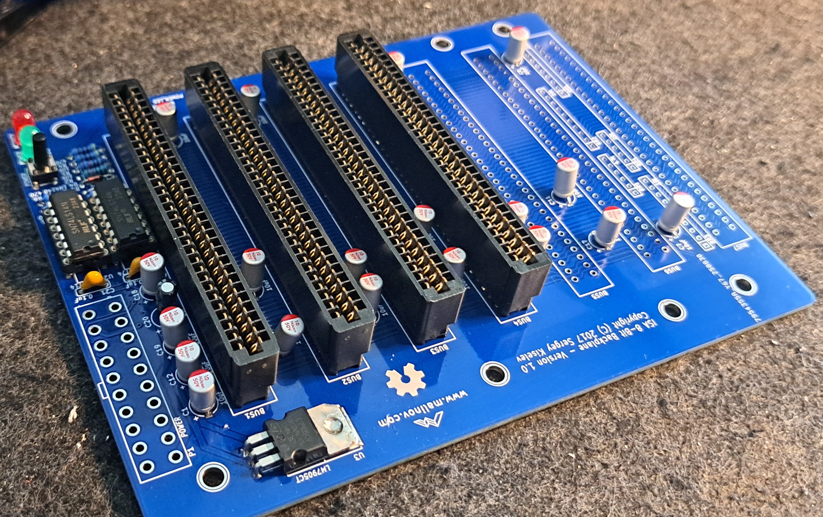
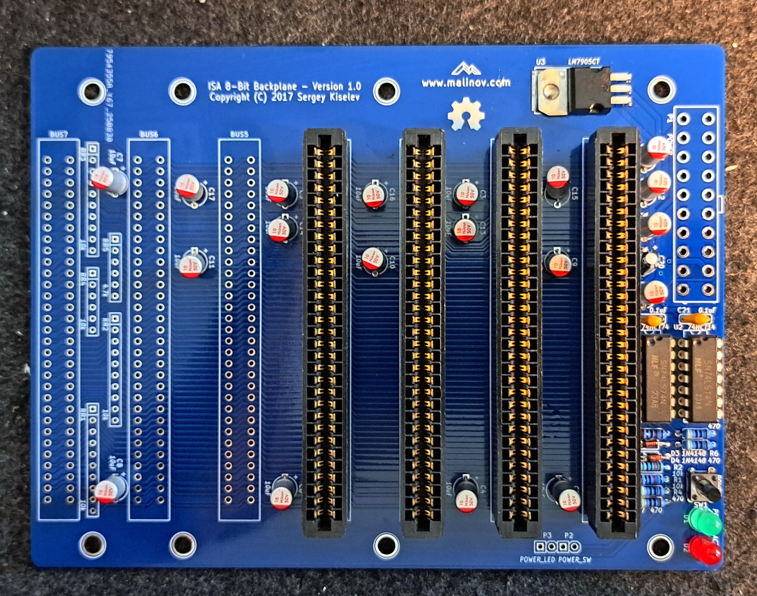
Here comes the circuit board, the one that all Sergey Kiselev Projects connect. The backplane consists of 7x 8-bit ISA slots, an ATX connector, two LEDs and a power button. Other than that, it doesn't have much more to offer apart from forming a real 8088 PC from all the 8-bit ISA cards.
Link to the project
Series contributions
ISA 8-bit 8088 Board – The main processor board with 8088 or V20
ISA 8-bit Backplane – Motherboard with ISA slots for the built ISA cards
ISA 8-Bit Super VGA Card – Card based on Trident TVGA9000i chip
ISA 8-bit Ethernet Card – Modern network card based on the Realtek 8019 chip
Views
Facts
- 7x 8-bit ISA slots
- Power LED / Activity LED
- Power button
- 20-pin ATX connector
- Pin header for power LED and button
- -5V voltage regulator to generate -5V from ATX power supply's -12V
Circuit diagrams
Documentation
No additional documentation is available, all information can be found on GitHub. Link to the project.
Assembly
Record
| Description | Worth |
|---|---|
| Gerber available | Yes |
| Gerber file | Link |
| Ordered where | JLCPCB |
| Piece | 5 |
| Price including tax and delivery | 25€ |
| Special features | Leedfree, Blue |
Here are the Gerber files saved. Please check the original site for anything newer.
Components
I ordered the components from various retailers. The price for one unit was around €20.
| Reference | Component type / Value | Quantity | Description | (approx.) Price in € | Check |
|---|---|---|---|---|---|
| ISA 8-Bit Backplane | 1 | I ordered mine from JLCPCB | £5.00 | ||
| U1 | 74HCT74 | 1 | Integrated Circuit (IC): DIP-14 Package Mouser 595-SN74AHCT74N | 0.60 EUR | |
| U2 | 74HCT14 | 1 | Integrated Circuit (IC): DIP-14 Package Mouser 595-SN74AHCT14N | 0.60 EUR | |
| U3 | LM7905C | 1 | Integrated Circuit (IC): -5V Voltage Regulator Mouser 512-LM7905CT | 0.50 EUR | |
| U1, U2 | DIP-14 | 2 | IC Socket: 300 mil socket Mouser 517-4814-3000-CP | 0.40 EUR | |
| D1 | 3 mm LED, blue | 1 | LED display Mouser 696-SSL-LX3054USBD | 0.30 EUR | x |
| D2 | 3 mm LED, two-colour red/green | 1 | LED display Mouser 696-SSL-LX3054IGW | 0.40 EUR | x |
| D3, D4 | 1N4148 | 2 | Diode Mouser 512-1N4148 | 0.20 EUR | x |
| SW1 | 6 mm | 1 | Short-stroke push button: Short-stroke push button, straight Mouser 653-B3F-1000 | 0.30 EUR | |
| Page 1 | ATX | 1 | Connector: 20-Pin power connector Mouser 538-46015-2006 | 0.80 EUR | |
| P2, P3 | Pen holder | 2 | Connector: 4-pin, 2.54 mm pitch Mouser 649-68002-104HLF | 0.20 EUR | |
| BUS1-BUS7 | ISA slot | 7 | Connector: 62-pin card edge connector, 2.54 mm pitch Mouser 571-6-5530843-5 | 3.80 euros | |
| C1 – C19 | 10 µF | 19 | Capacitor: 16V, MLCC, 5 mm pitch Mouser 810-FG28X5R1E106MR06 | £1.20 | |
| C20 | 1 µF | 1 | Capacitor: MLCC, 5 mm pitch Mouser 810-FG28X5R1H105KRT0 | 0.20 EUR | |
| C21, C22 | 0.1 µF | 2 | Capacitor: MLCC, 5 mm pitch Mouser 594-K104K15X7RF53H5 | 0.20 EUR | |
| R1, R2 | 10 kOhm, wired | 2 | Resistance Mouser 291-10K-RC | 0.30 EUR | x |
| R3 | 1 kOhm, wirewound | 1 | Resistance Mouser 291-1K-RC | 0.30 EUR | x |
| R4 – R7 | 470 Ohm, wirewound | 4 | Resistance Mouser 291-470-RC | 0.30 EUR | x |
| RR1 – RR5 | Resistor network: do not populate (Optional, should not be populated.) | 0.00 EUR | – | ||
| Total material costs (guideline value) | 17.00 EUR |
Structure
Variations
Recommended logic family CMOS 74HCT series
- Possible alternatives: 74AHCT or 74ACT
- TTL-ICs (74LS, 74ALS, 74F) work but consume more power.
LEDs
- Power LED (D1): Recommended 3mm blue LED; 5mm or other colours also work
- Activity LED (D2): recommended 3 mm red/green bi-colour LED with two connections (antiparallelly connected LED crystals)
Capacitors
- Recommended: Ceramic multilayer capacitors with 5 mm pitch
- 2.5 mm pitch or axial capacitors can be adapted by bending the leads
- Electrolytic or tantalum capacitors for C1–C19 (10 µF) are possible — Observe polarity!
Order
The instructions on Github were more detailed than I would have written them, so I've translated them, changed the order slightly, and reproduced them here. This way to the original.
- Check circuit board for visible defects (scratches, short circuits)
- Clean PCB with alcohol
- Solder components from low to high
- Solder diodes D3 and D4 in place — Consider polarity (Black ring = marking)
- Solder resistors R1–R7
- Voltage regulator U3 shape and solder in — hole for heatsink must align with PCB hole
- Solder capacitors C1–C22 — Consider polarity, falls polarised
- Solder in DIP sockets U1 and U2 — Observe alignment
- Solder LEDs D1 and D2 Note polarity at D1
- Solder pin headers P2–P3
- Solder switch SW1
- Solder ATX power connector P1
- Solder ISA card connectors BUS1–BUS7
- Carefully check all solder joints; re-solder if necessary.
- Optional: Check for short circuits and supply voltages with a multimeter
- Clean the board thoroughly with alcohol, wipes, and a toothbrush
- Carefully insert ICs into the sockets — align pins on a hard, non-static surface if necessary
- Check the orientation of the ICs; ensure no pins are bent
- Re-inspect finished circuit board
- Install Micro-8088-Board and other ISA cards, connect power supply
- Turn on, test, install software — and have fun!
Commissioning
You can supply power to the backplane, and you should do so before plugging in a card, but otherwise, it can't do much itself. It's more of a link.
Miscellaneous
Data sheets
7474
Source: https://www.alldatasheet.com/view.jsp?Searchword=7474
7414
Source: https://www.alldatasheet.com/datasheet-pdf/pdf/27375/TI/7414.html
General Tips
Soldering points
Check the solder joints on the ICs again carefully, preferably with a microscope or magnifying glass, for short circuits and contact. Measure with a multimeter or continuity tester.
For small solder joints on through-hole components, use flux if possible; it makes life easier and increases the quality of the connection.
Problems
Conclusion
| Description | Worth |
|---|---|
| Successful | Yes |
| Price per piece | ~20€ |
| Soldering time | 1 hour |
| Function | Gut |
| Is it worth it | Yes, a nice addition to the set |
| Restrictions | 8-bit, no additional functionality |
Related Posts
- Retro Project – Voltage Blaster
- Retro Project – 8-Bit ISA Ethernet Card (isa8_eth)
- Retro Project – FDC USB Floppy Disk Controller
- Retro Project – Floppy Disk Controller (isa-fdc)
- Retro Project – ROMOS
- Retro Project – USB to RS232 Mouse Adapter
- Retro Project – Monotech ISA Double ROM
- Retro Project - Greaseweazle 4.1
- Retro Project – ATX Form Card
- Retro Project – ISA Boot EEPROM Card
Sources
To the project
Retro pages
https://archive.org – Old software, magazines, manuals, and much more.
https://theretroweb.com – PC Hardware Directory.
https://www.winhistory.de/index.php – DOS, Windows Version Descriptions.
Win 3.1x Tools and Tricks
Retro Forensics
https://forum.classic-computing.de/forum – German/English forum with many retro computer enthusiasts.
https://www.vogons.org – I have found many tips on hardware here, they also have a driver directory.
https://www.dosforum.de – Forum with strict rules and very helpful regarding DOS, Windows questions are not welcome.
https://dosreloaded.de – DOS, hardware repairs, BIOS files and more.
https://www.winhistory-forum.net DOS and Windows history.
Retro Shops
https://ram-co-shop.de - PC parts, including newer ones, have ordered a lot from there and it's always worked.
http://www.amoretro.de – Sold on eBay and has a nice directory of old hardware
https://retroreiz.de – Atari, Nintendo, Sega and others.
https://www.retroworld.info/de – Stickers, signs and more.
https://retesa-nb.de – Older PC hardware
https://www.retro8bitshop.com – C64 tricky
Logbook
| Date | Description |
|---|---|
| 30.08.2025 | Post created and PCB ordered. |
| 09.09.2025 | Boards arrived |
| 20.06.2025 | Gathered stuff |
| 21.06.2025 | Soldered the board, unfortunately I'm missing the 20-pin ATX connector. I only have a 24-pin one that I could shorten, but I'd rather wait until the ordered one arrives. |