Last Updated on 4. October 2026 by SuffocationLink status: OK
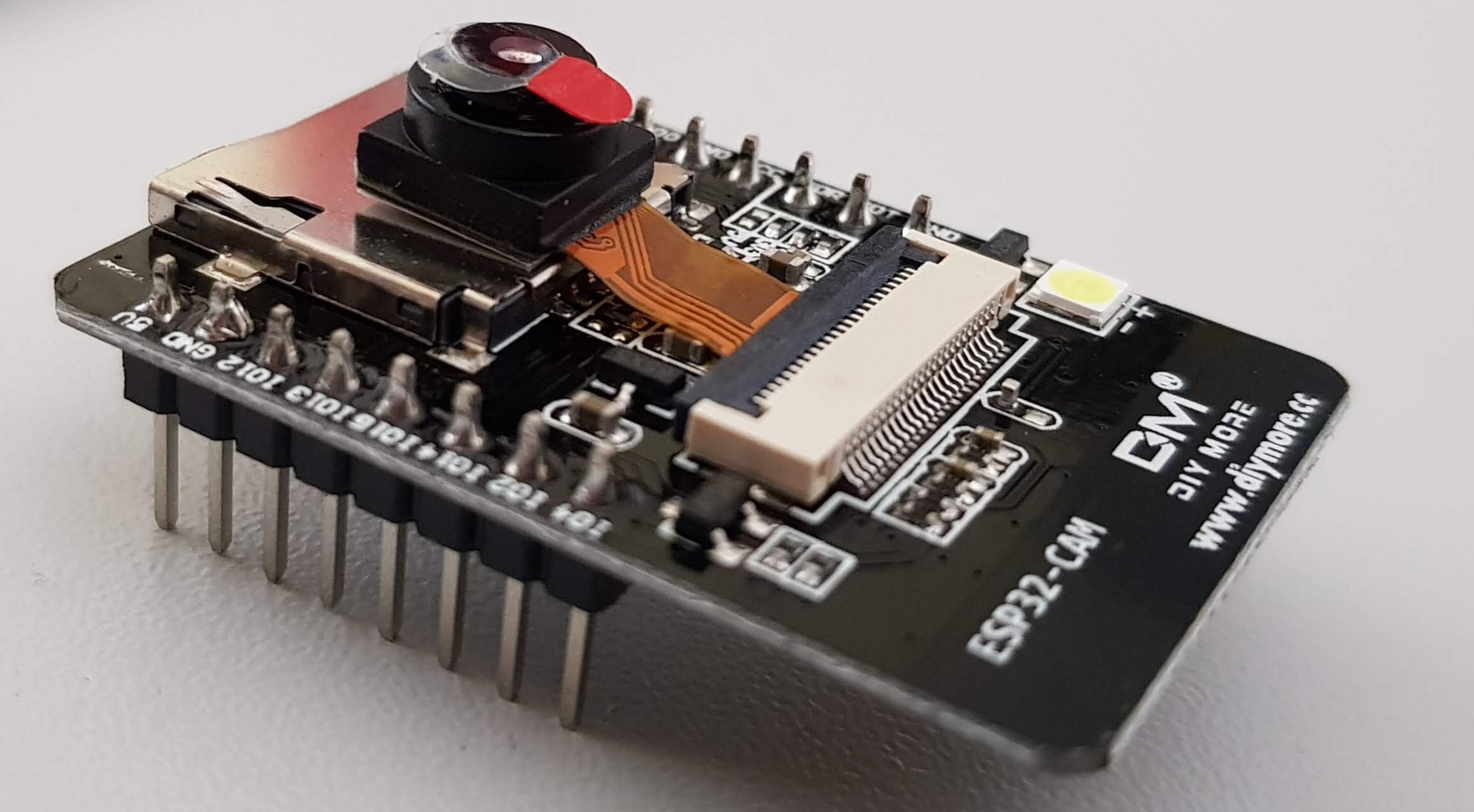
Beim schnellen Ali habe ich ein ESP 32 Modul mit Kamera für unter 10€ gefunden. Dieses stelle ich hier kurz vor und zeige die ersten Schritte.
Facts
Neben allem, was der ESP32 sowieso bietet, hier noch ein paar zusätzliche Eigenschaften.
- Space for an SD card
- 520 KB SRAM + external 4MB PSRAM
- Support OV2640 and OV7670 cameras
- OV7670 Camera Module
- Flash
CautionThe pinout may vary, it's best to check the CAM again.
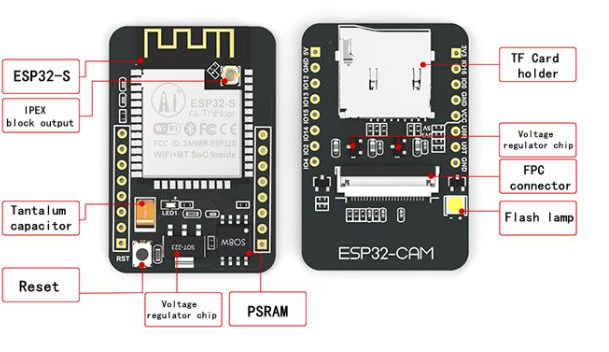
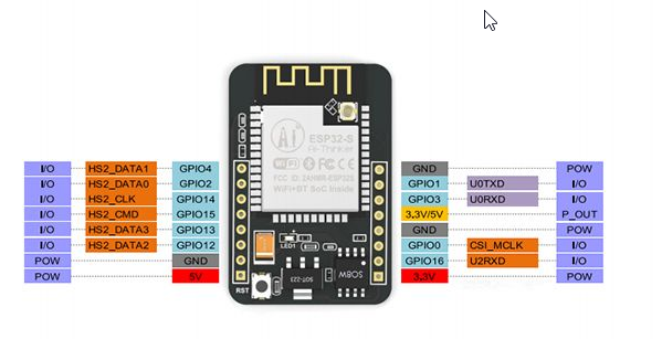
Camera connections
| OV2640 Camera | ESP32 | Variable name in code |
| D0 | GPIO 5 | Y2_GPIO_NUM |
| D1 | GPIO 18 | Y3_GPIO_NUM |
| D2 | GPIO 19 | Y4_GPIO_NUM |
| D3 | GPIO 21 | Y5_GPIO_NUM |
| D4 | GPIO 36 | Y6_GPIO_NUM |
| D5 | GPIO 39 | Y7_GPIO_NUM |
| D6 | GPIO 34 | Y8_GPIO_NUM |
| D7 | GPIO 35 | Y9_GPIO_NUM |
| XCLK | GPIO 0 | XCLK_GPIO_NUM |
| PCLK | GPIO 22 | PCLK_GPIO_NUM |
| VSync | GPIO 25 | VSYNC_GPIO_NUM |
| HREF | GPIO 23 | HREF_GPIO_NUM |
| Seventh-day Adventist | GPIO 26 | SIOD_GPIO_NUM |
| SCL | GPIO 27 | SIOC_GPIO_NUM |
| POWER PIN | GPIO 32 | PWDN_GPIO_NUM |
SD card slots
| MicroSD card | ESP32 |
| CLK | GPIO 14 |
| Command Prompt | GPIO 15 |
| DATA0 | GPIO 2 |
| DATA1 / flashlight | GPIO 4 |
| DATA2 | GPIO 12 |
| DATA3 | GPIO 13 |
Additional pins
| Description | Pin |
| Blitzlicht (Doppelbelegung mit SD – DATA1) | 4 |
| Potentially free pins | 1, 3, 16 |
| Red LED on the back (LOW active) | 33 |
Areas of application
- Webcam
- Observation camera
- Visual Navigation
- Facial recognition
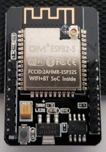
Views
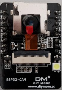
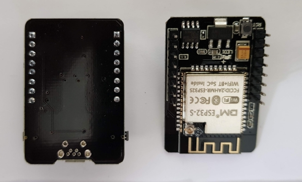
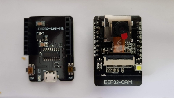
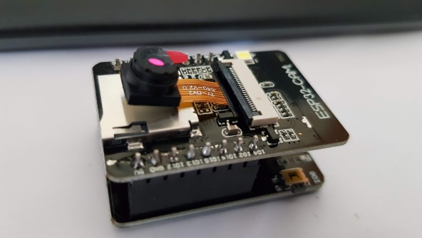
Analyse
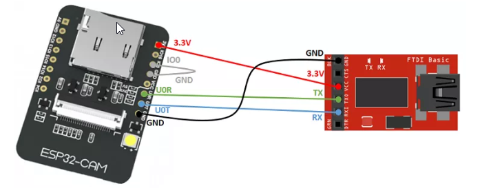
Das Board kommt leider ohne ISP Programmierer und somit ohne USB Anschluss. Somit ist ein wenig Vorarbeit nötig, um den ESP zu programmieren.
Zuerst wird ein ISP oder ein simpler USB to Serial Konverter benötigt. Ich verwende einen FTDI vom schnellen Ali (LinkLink status: OK).
ACHTUNG! vor dem ersten Betrieb sicherstellen, dass der FTDI auf 3.3V eingestellt ist.
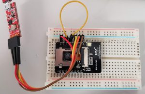
Die Verkabelung ist schlicht, für den Aufbau verwende ich ein Steckbrett und ein paar Pinheader Kabel. Zuerst stelle ich die Strom Verbindung her, hierfür müssen jeweils die 3,3V und die Masse (GND) des FTDI mit denen des ESP verbunden werden. Danach müssen noch die beiden Datenleitungen (RX/TX) angeschlossen werden. Die Verbindung zwischen Masse und IO0 muss zum Programmieren gesteckt und danach wieder entfernt werden. Vor dem Programmieren empfiehlt sich ein Reset. Siehe hierzu auch das folgende Bild.
Programming
Libraries
The Arduino IDE must be prepared for the ESP32. More information on this via the following link:
The camera web server and camera drivers are included in the ESP installation, but those looking for the latest version can find it at the following links:
Camera driverLink status: OK
Webcam serverLink status: OK
Test programme
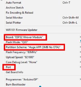
There is an example program for the camera. First, select the correct ESP.
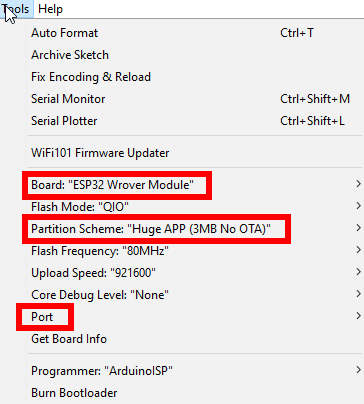
TIP: Sollte es Probleme beim Compilieren oder danach mit Exceptions geben, schaut mal im Kapitel Probleme nach.
Dann erscheinen die passenden Beispielprogramme im Menüpunkt „Examples“. Für den ersten Test habe ich den CameraWebServer ausgewählt:
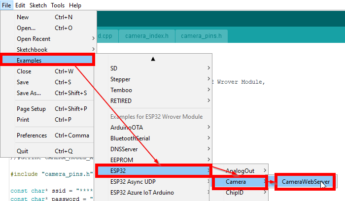
Enter the SSID and password for the local Wi-Fi in the program and #define CAMERA_MODEL_WROVER_KIT auskommentieren sowie #define CAMERA_MODEL_AI_THINKER reinnehmen.
Compile the program and load it onto the ESP. After a reset, it looks like this on the console:
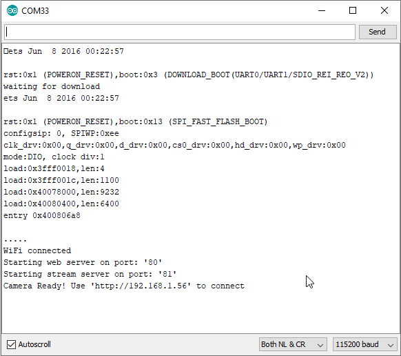
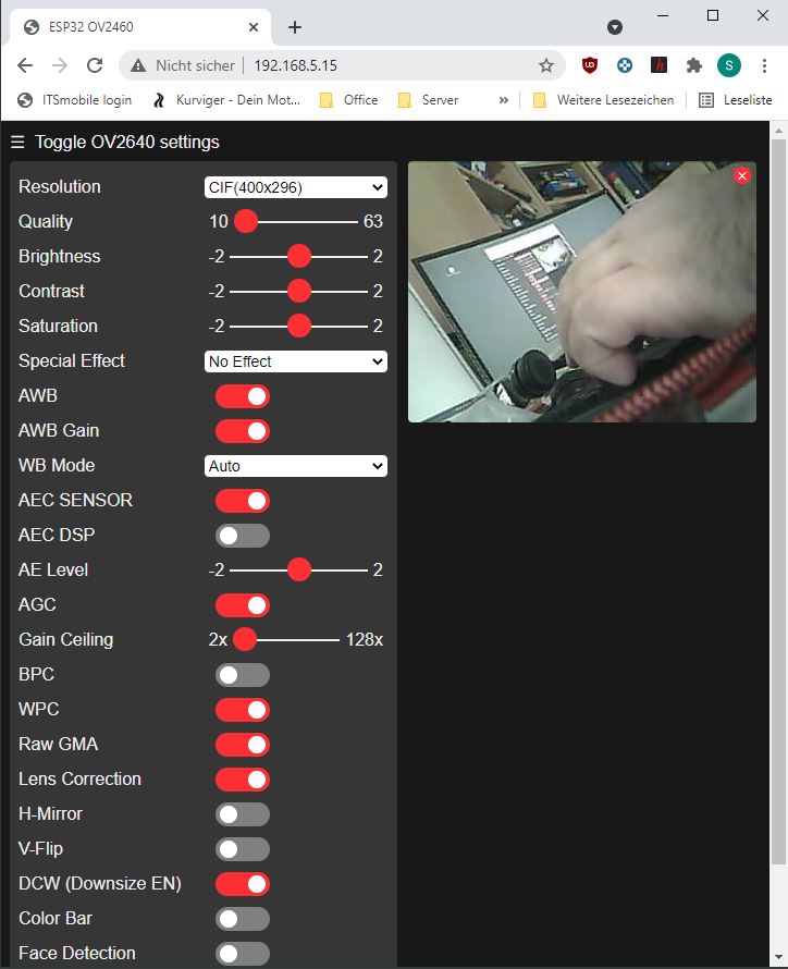
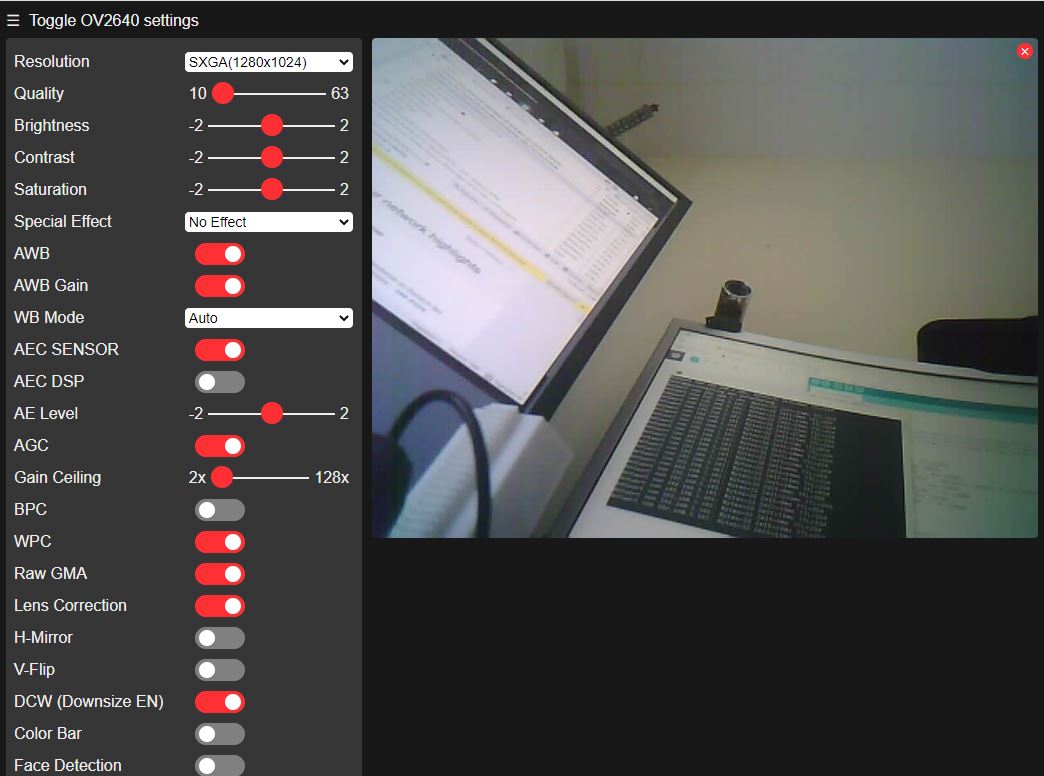
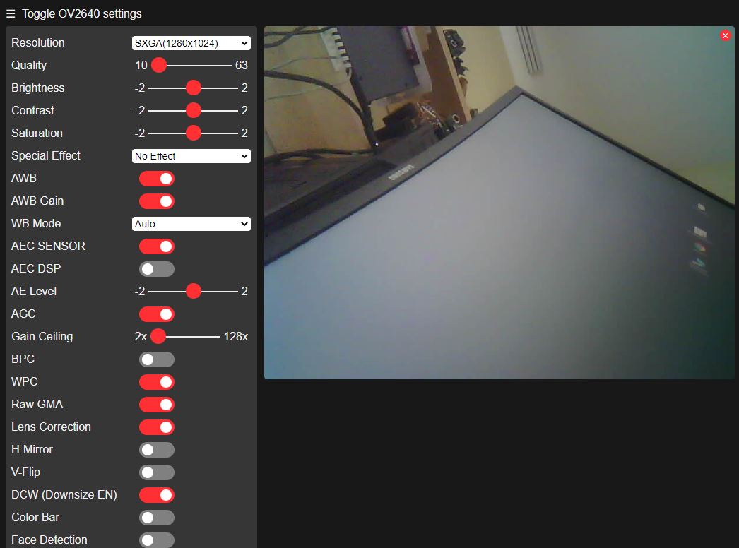
Ganz unten ist die IP Adresse zu sehen, über welche der ESP im Netzwerk verfügbar ist. Diese in einen Browser eingeben und nach kurzer Wartezeit erscheint die Steuerzentrale:
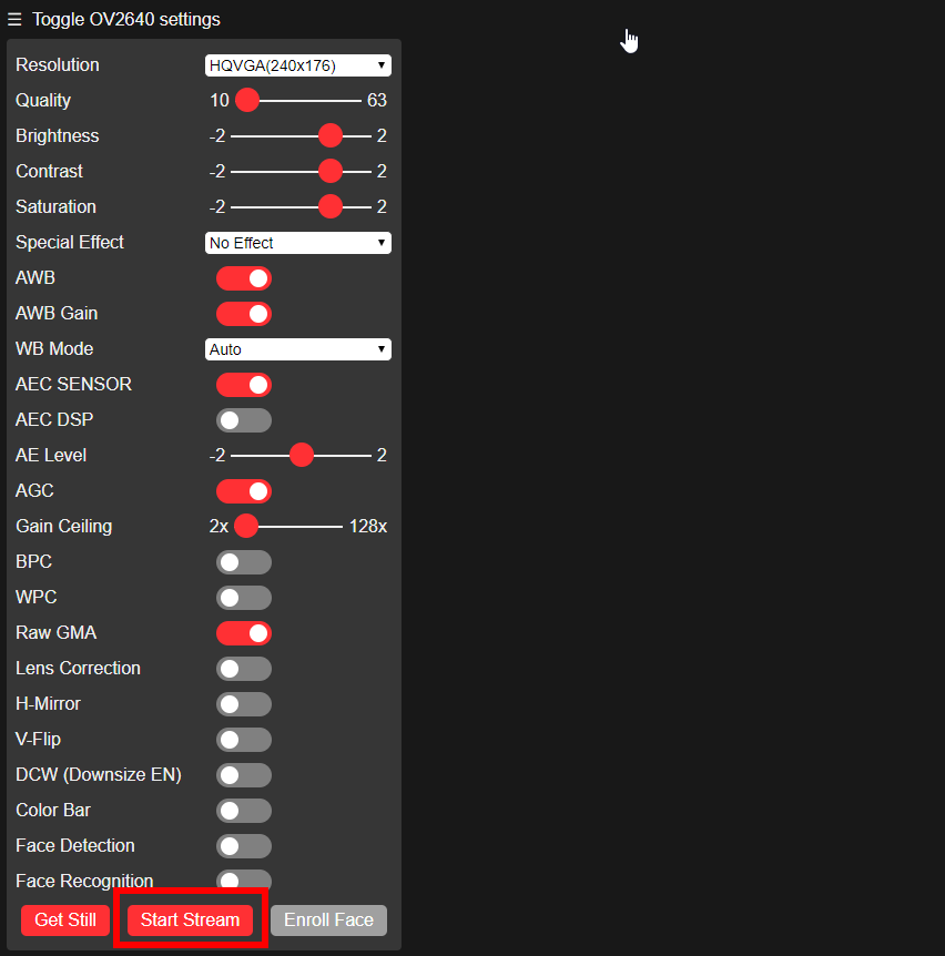
Noch den Stream starten und siehe da, es kommt ein Bild:

Wer eine alternative Firmware sucht, kann es mal mit der folgenden probieren: RTSP source for the ESP32CamLink status: OK.
Problems
The writing to the ESP isn't working
Wenn beim Upload auf den ESP die GUI mit Timeout Fehler aussteigt, mal den Reset-Taster betätigen:
- Start Upload
- Wenn „Connecting“ in der Ausgabe steht, den Reset Taster kurz drücken.
Zusätzlich checken, ob der GPIO mit Masse verbunden ist und der RX und der TX Eingang richtig verbunden sind, eventuell mal tauschen.
Camera not recognised error 0x20004
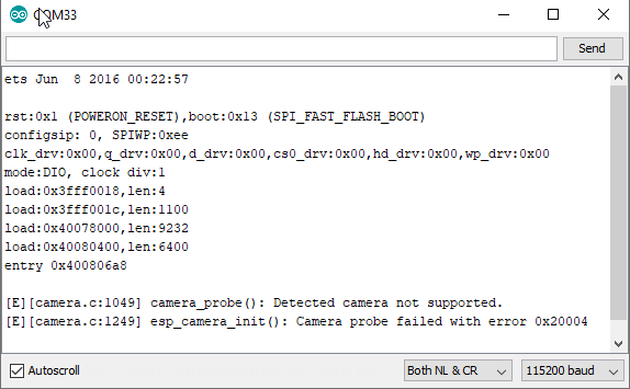
Falsches Kamera Pinning ausgewählt, für mein Modell benötigte ich:
#define CAMERA_MODEL_AI_THINKERZusätzlich musste ich das Modul mit 5V (am 5V Anschluss) betreiben, da 3V zu wenig waren.
Lines in the camera image
Lars (Siehe Kommentare unten) hat ein paar Versuche gemacht. Es hat sich als vorteilhaft herausgestellt, das Modul am 5V Anschluss zu betreiben.
On-board storage too small
Checkt die Board-Einstellungen, hier muss Partition Scheme = „Huge App … No OTA“ eingestellt sein (Zweiter roter Kasten).
Brownout detector was triggered
„Brownout detector was triggered“ hatte ich bis jetzt nur, wenn ich keine externe Spannungsquelle am Gerät hatte. evtl. reicht auch ein besseres USB Kabel zu verwenden. Der VIN ist mit 5V angegeben, ich habe hier schon 6V und mehr angeschlossen, der Spannungswandler konnte damit umgehen, ist aber sehr heiß geworden. Tipp natürlich ohne Gewähr ;). Der folgende Link könnte auch noch weiterhelfen:
Exceptions after uploading the program
Peter berichtet (siehe Kommentar unten), dass er nach dem Programmieren nur Exceptions mit der oben angegebenen Konfiguration bekommt.
It worked for him with the TTGO T1 board.
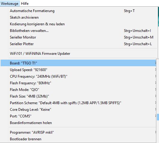
Ohne mein geschriebenes von oben zu beachten, habe ich meine letzte Kamera mit der folgenden Konfiguration erfolgreich compiliert und getestet.
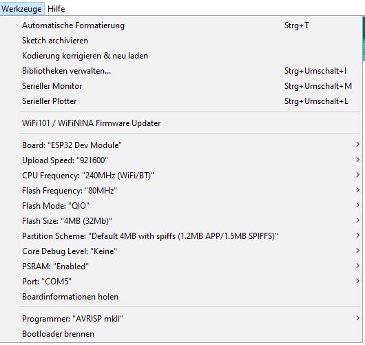
I switched on the PSRam usage specifically; however, this might lead to problems on other boards.
[E][camera.c:1344] esp_camera_fb_get()
Alias „Horst“ (Siehe Beitrag unten) berichtet eine Framebuffer Exception mit der folgenden Kamera ESP Kombi und der ESP32-Cam. Der Unterschied zu meiner ist der Aufdruck auf dem Flachbandkabel ( TY-OV2640 V2.0). Es wäre möglich, dass es an der Version 2 liegt.
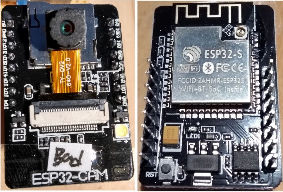
Die Kamera funktioniert wohl mit dem mitgelieferten esp-cam demo und compiliert unter der ESP-IDF v3.3-beta1-506-gebdcbe8c6 vom 5. März 2019. Ich vermute, dass es sich hierbei um Igors demo handelt (ist ne ältere Version der ESP32-CAMLink status: OK):
https://github.com/igrr/esp32-cam-demoLink status: OK
Das FB Problem scheint noch weitere Auslöser zu haben. So gibt es einige Bug Reports hierzu (siehe unten). Manche melden Erfolge bei Verringerung der Frequenz von 20MHz auf 10Mhz:
 //XCLK 20MHz or 10MHz for OV2640 double FPS (Experimental)
    .xclk_freq_hz = 20000000,
Bug Reports
https://github.com/espressif/esp32-camera/issues/155Link status: OK
https://github.com/espressif/esp32-camera/issues/93Link status: OK
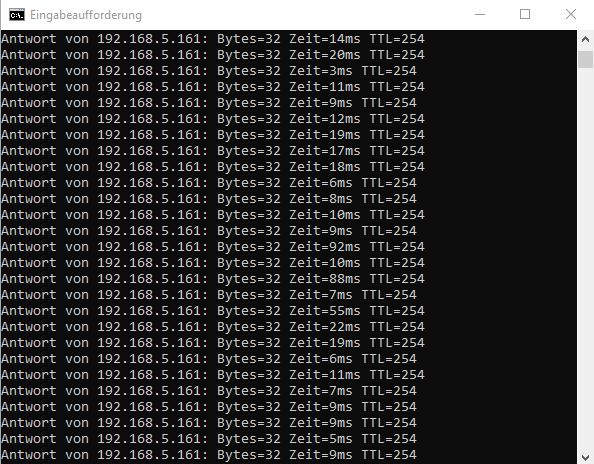
Ping dropouts
It has been reported by Patrick (see comments below) that there are ping dropouts.
Ich habe ein paar Pingtests mit unterschiedlichen Modulen, Auflösungen, mit und ohne Stream getestet. Ich konnte das Problem leider nicht nachstellen. Bitte schreibt einen Kommentar, wenn ihr ähnliche Probleme habt oder sogar ne Lösung.
QM DIY More:
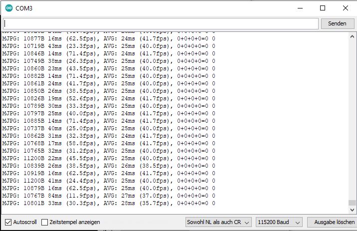
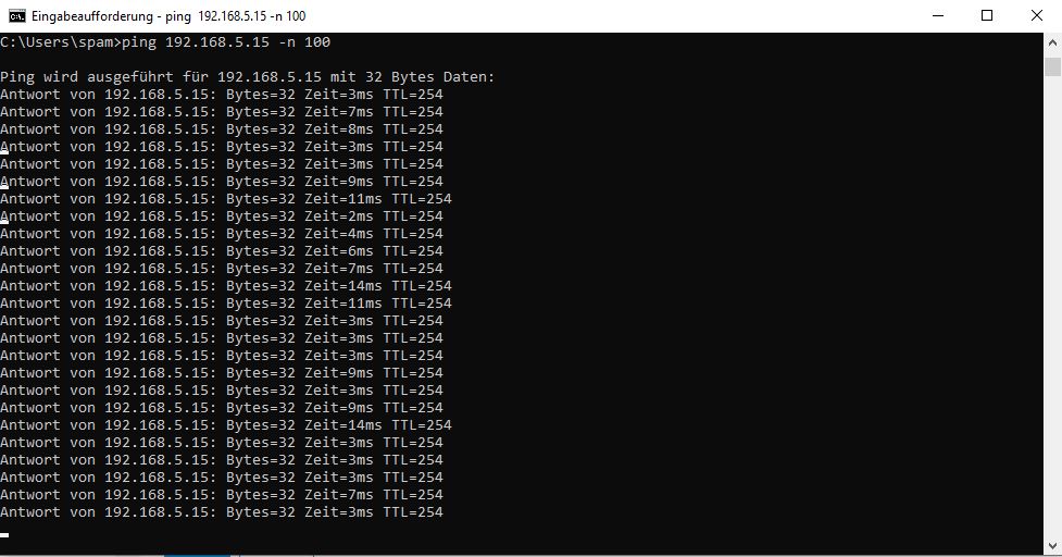
ESP32-CAM HW818 (With onboard USB)
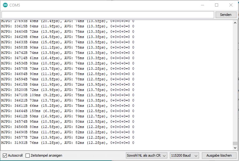
ESP32-CAM + ESP32-CAM-MB
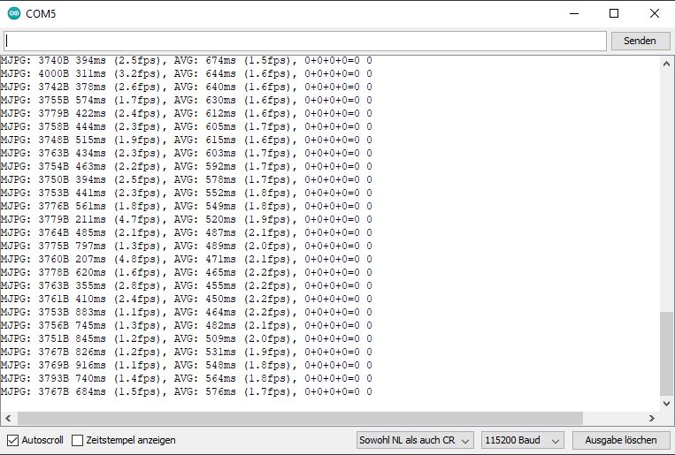
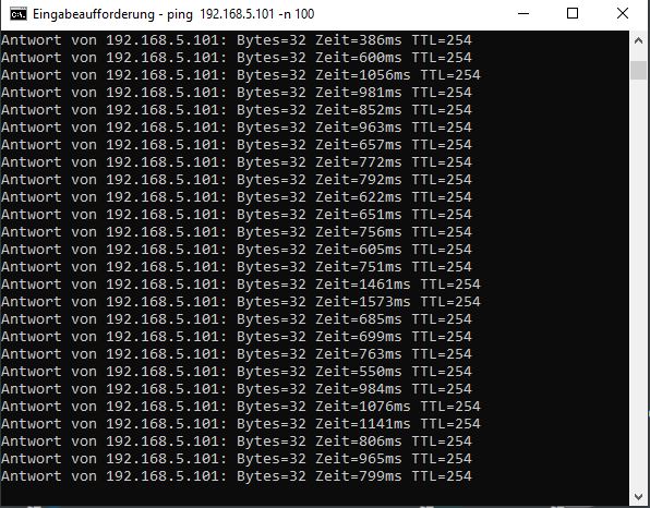
The pings are much worse here:
Miscellaneous
Streaming
Der Esp-Stream ist auf dem Port 81 verfügbar. Hier können Streaming-Clients das Signal abgreifen. Das Format ist MJPEG und die URL ist wie folgt aufgebaut:
http://:81/streamLink status: Unknown
Da der aktuelle Beitrag immer länger wird, habe ich die einzelnen TOOLCHECKS in eigene Beiträge umgewandelt. Der Test mit dem VLC war bei mir leider nicht erfolgreich. Für alle, die unter Linux arbeiten, hat Joseph (See comments below) recommended the MPV Player, for which there is now a dedicated post.
- Raspberry Pi as NVR with ShinobiLink status: OK
- MPV (Linux)Link status: OK
- ISpyLink status: OK
- VLC Media PlayerLink status: OK
Es gibt noch weitere Streaming Clients, mit denen ist sicherlich analog zu verfahren.
Remote camera control
Der Webserver erlaubt es, die Kamera mittels HTTP Anfragen zu steuern. Der generelle Aufruf lautet wie folgt:
http://<ip>/control?var=<Variablenname>&val=<Wert>
Possible combinations
Einige Variablen/Wertkombinationen habe ich in der folgenden Tabelle aufgeführt. Die Funktionen, deren Arbeitsweise ich nicht verstanden habe, sind mit einem „?“ markiert:
| Description | Variablenname | Values |
| Resolution | Framesize | 10 UXGA(1600×1200) 9 SXGA(1280×1024) 8 XGA(1024×768) 7 SVGA(800×600) 6 VGA(640×480) 5 CIF(400×296) 4 QVGA(320×240) 3 HQVGA(240×176) 0 QQVGA(160×120) 4 Default |
| Image quality | Quality | 10 good to 63 bad 10 Pre-set |
| Brightness | Brightness | -2 to 2 0 Preset |
| Contrast | Contrast | -2 to 2 0 Default |
| Saturation | saturation | -2 to 2 0 Preset |
| Special effects | special effect | No effect 1 Negativbild 2 Schwarz/Weiss 3 Red complexion 4 Green complexion 5 Blue complexion 6 Sepia 0 Preset |
| Toggle white balance | Air Waybill | 0 off 1 A 1 Default |
| Spezielle Funktionen für den Use white balance. Or | AWB Gain | 0 off 1 A 1 Default |
| White balance Functions | wb_mode | 0 Auto 1 Sunny 2 Cloudy 3 Offices 4 Home 0 Default |
| AEC SENSOR | aec | 0 off 1 A 1 Default |
| AEC DSP | aec2 | 0 off 1 A 1 Default |
| A-Level | AE level | -2 to 2 0 |
| Exposure? (not visible to me) | aec_value | 0 – 1200 204 |
| Toggle between the the following functions agc_gain und gainceiling | AGC | 0 Gain 1 Gain-Ceiling 1 Default |
| agc\_gain-group? | agc_gain | 0 Simple 30 31 fold 5 |
| gainceiling-group? | Gain ceiling | 0 two-fold Up 6 128 professional 0 |
| BPC | BPC | 0 off 1 An 0 Default |
| WPC | WPC | 0 off 1 An 1 Default |
| Raw GMA? | raw_gma | 0 off 1 An 1 Default |
| Linsen Korrektur? | len | 0 off 1 An 1 Default |
| Horizontale Spiegelung If the camera is on the side is located = Vertical) | Mirror | 0 off 1 An 1 Default |
| Vertical mirror If the camera is on the side Horizontal | Flip vertically | 0 off 1 An 1 Default |
| DCW (Downsize EN) ? Shrink the image | dcw | 0 off 1 An 1 Default |
| Display colour bars the screen | Colourbar | 0 off 1 An 0 Default |
| Gesichtssuche aktivieren | face detect | 0 off 1 An 0 Default |
| Enable face recognition | face_recognise | 0 off 1 An 0 Default |
Examples:
Die Beispiele könnt ihr einfach in die Adressleiste eures Browsers kopieren. Vom Webserver kommt keine Antwort zurück, ob es geklappt hat oder nicht. Bitte die IP durch die eurer Kamera tauschen.
Auflösung auf VGA stellen:
http://192.168.1.66/control?var=framesize&val=6
Degrade image quality
http:// 192.168.1.66/control?var=quality&val=20
Adjust brightness
http:// 192.168.1.66/control?var=brightness&val=2
3D Printed Housing / Pan Tilt
Here are a few links to cases:
https://www.yeggi.com/q/esp32+cam/Link status: Unknown
https://www.thingiverse.com/search?q=esp+cam&type=things&sort=relevantLink status: OK
Den folgenden Pan/Tilt habe ich mal ausgedruckt.
https://www.thingiverse.com/thing:3579507Link status: OK
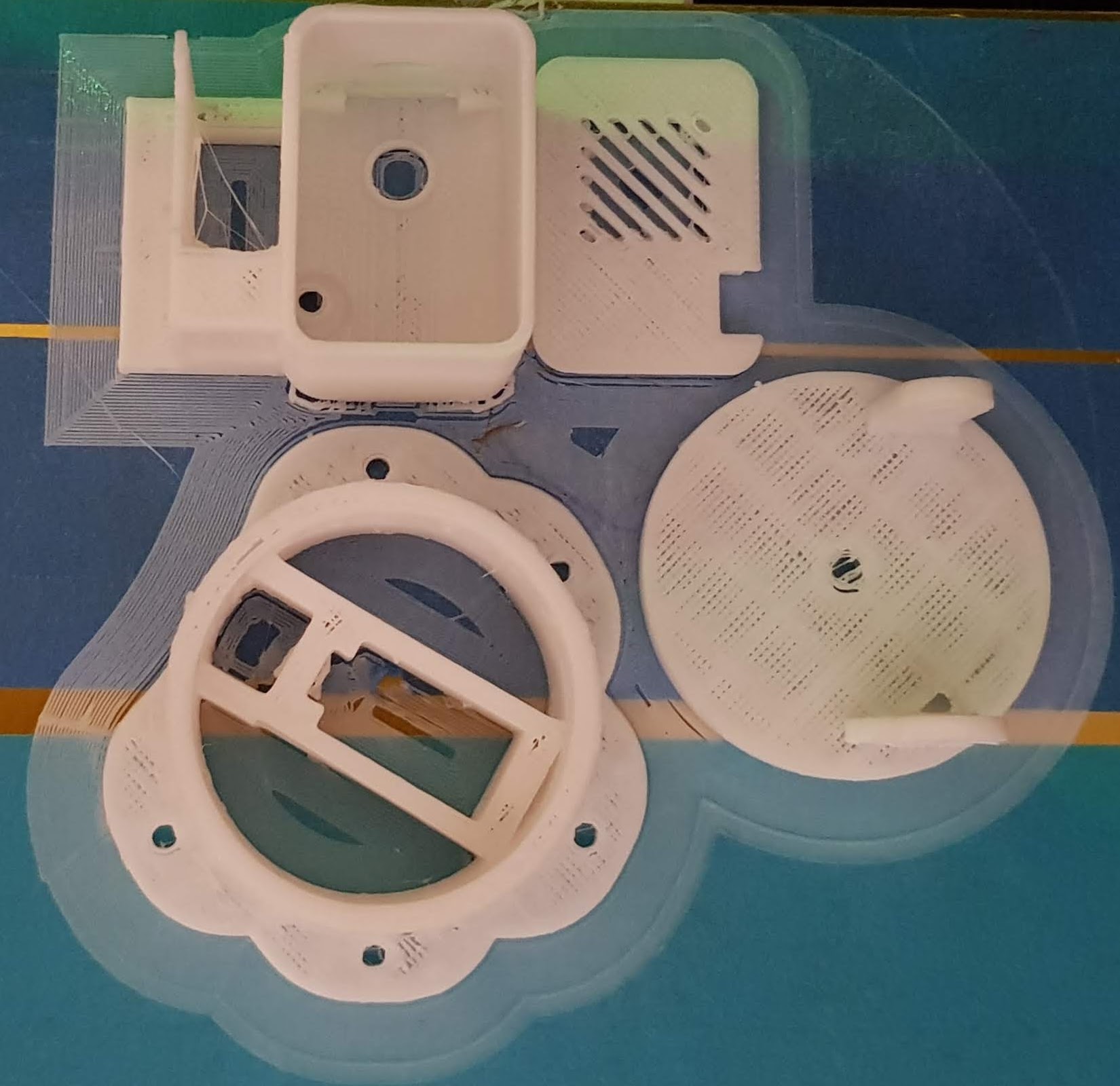
Source: https://www.thingiverse.com/thing:3579507Link status: OK
For those who need it, here's the lid detached from the composite.
Dafür, dass ich dünne Außenwände und schnelles Drucken verwendet habe, passen die Teile ganz gut zusammen. Bei mir hängt der Deckel zum Drehen des Kopfes etwas in der Luft, hier wäre eine schönere Befestigung des Servo Kopfes denkbar. Auch hatte ich keinen Draht oder Büroklammer, die ich opfern konnte, zur Hand, deshalb ist die Konstruktion zum Neigen des Kopfes nicht optimal. Wie man dem kleinen Video entnehmen kann, funktioniert der Pan/Tilt dennoch so wie es soll. Auch die ESP Cam passt exakt in die Aussparung.
ESP as a camera viewer
Sigi (Siehe Kommentare) hat die Frage aufgebracht, ob ein ESP auch als Viewer für die Kamera dienen könnte. Nach vorheriger Abwägung und ein paar Tipps von Lars habe ich meine eigene Version des M5 Stack Viewers erstellt:
Free pins
Die Cam bietet kaum nach außen durchgeschleifte Pins. Nach Abzug des Programmers müssten GPIO1, GPIO3 und evtl. GPIO16 frei sein. GPIO1/3 werden allerdings auch für die serielle Schnittstelle benötigt. GPIO16 habe ich noch nicht getestet.
Der ESP32 hat schon eine Menge Pins, evtl. könnte man hier auch direkt auf den ESP gehen. Die folgende Seite hat mir sehr geholfen, deshalb möchte ich sie euch nicht vorenthalten:
Es ist wohl möglich, die SD Karte mittels der Fuses auf einen Ein-Leitungs-Betrieb umzustellen. Dies befreit den Port 12 und 13.
The command for the console is as follows:
espefuse.py –baud 115200 –port **your_USB_port_name** set_flash_voltage 3.3V
https://randomnerdtutorials.com/esp32-cam-ai-thinker-pinout/Link status: OK
Here's more on the 1-wire mode of the SD card.Link status: Unknown
The LinkLink status: Unknown could also help.
Alternatively, you might want to look at these camera models:
https://github.com/lewisxhe/esp32-camera-seriesLink status: Unknown
Https://github.com/Xinyuan-LilyGo/esp32-camera-screenLink status: Unknown
Im folgenden Link hat jemand einen PIR an die Kamera angeschlossen. Ports mit Hilfe des 1-wire Betriebs der SD Karte freigeschaltet.
https://github.com/jameszah/ESP32-CAM-Video-Recorder/blob/master/demo_fritz2.jpgLink status: Unknown

Extend camera cable
Soweit ich das der Spezifikation entnehmen konnte, ist die Kamera eine OV2640 mit 24 Pins mit FFC Kabel 0,5 mm Raster. Für verschiedene Projekte wird die Kamera an anderer Stelle als die Platine benötigt. Es gibt hierfür Verlängerungen oder Kameras mit längerem Kabel. Wobei die Kameras mit längerem Kabel fast günstiger erscheinen.
Camera from Speedy Ali, with a longer cable.Link status: Unknown
Another fish eye from Fast AliLink status: Unknown
FFC Kabel Suche in der elektronischen BuchtLink status: Unknown
Ob die Verlängerung funktioniert, habe ich noch nicht ausprobiert, ist also eher ein Versuch, sollte aber klappen, solange das Kabel nicht zu lange wird.
Projects
Read the water meter
Lars writes (see comments) about a nice project which reads values from a water meter using ESP32 image recognition.
Pan-tilt
Conclusion
It works, you can operate a camera with the ESP32. The setup is straightforward for experienced hobbyists.
Es gibt ein paar Fallstricke, siehe hierzu auch das Kapitel „Probleme“. Die Bildqualität überzeugt nicht wirklich, evtl. ist hier noch die ein oder andere Optimierung möglich oder meine Hardware ist nicht ganz OK.
Das Testprogramm ist für einen ersten Test überragend, es bietet viele Einstellmöglichkeiten bis hin zu einer Gesichtserkennung. Da hat sich jemand richtig Mühe gegeben.
Related Posts
- Raspberry Pi as NVR with ShinobiLink status: OK
- TTGO T-Camera ESP32 (V162/V17)Link status: OK
Sources
RTSP source for the ESP32CamLink status: OK
https://www.diymore.ccLink status: Unknown
Source: https://randomnerdtutorials.com/esp32-cam-ai-thinker-pinout/Link status: OK
Link ins FHEM Forum zum gleichen Thema, gepostet von Papa_Romeo (Siehe Kommentar), da wurde sich schon ausführlich mit der Materie befasst. Schaut doch einfach auch mal dort rein. https://forum.fhem.de/index.php/topic,95604.msg884592.html#msg884592Link status: Unknown
Further links from the forum itself:
https://robotzero.one/Link status: Unknown
https://randomnerdtutorials.com/Link status: OK
https://robotzero.one/esp32-face-door-entry/Link status: Unknown
https://robotzero.one/esp-who-recognition-with-names/Link status: OK
https://www.instructables.com/id/Video-Capture-Using-the-ESP32-CAM-Board/Link status: Broken
https://www.thingiverse.com/thing:3579507Link status: OK
https://www.thingiverse.com/search?q=esp+cam&type=things&sort=relevantLink status: OK
https://www.yeggi.com/q/esp32+cam/Link status: Unknown
https://www.videolan.org/vlc/index.de.htmlLink status: OK
https://github.com/geeksville/TenDollarWebcamLink status: OK
https://github.com/espressif/esp32-cameraLink status: OK
https://circuitdigest.com/microcontroller-projects/how-to-use-esp32-camera-module-for-video-streaming-and-face-recognitionLink status: OK
https://github.com/espressif/esp32-cameraLink status: OK
https://github.com/easytarget/esp32-cam-webserverLink status: OK
https://randomnerdtutorials.com/esp32-troubleshooting-guide/Link status: OK
https://github.com/jameszah/ESP32-CAM-Video-RecorderLink status: OK
https://github.com/moononournation/M5Stack-Cam-ViewerLink status: OK
https://github.com/raphaelbs/esp32-cam-ai-thinkerLink status: OK
https://github.com/xenpac/ESP32-CAM-Linux-MotionLink status: OK
| Date | Change | Author |
|---|---|---|
| 04.10.2026 | Rechtschreibung korrigiert: Tippfehler, Kommas, Groß-/Kleinschreibung, Grammatik | Suffocation |
| 03.10.2026 | Log-Liste eingefügt | Suffocation |
| 14.09.2019 | Post created | Suffocation |
Hello, I have a question. Can a servo control (Pan/Tilt) be put into the sketch https://randomnerdtutorials.com/esp32-cam-shield-pcb-telegram/
e.g. something like that https://randomnerdtutorials.com/esp32-cam-pan-and-tilt-2-axis/ install or is the control of the servos generally not possible via Telegram then? I'm not very experienced in this area yet, but maybe someone can give me a tip.
Mfg. Uwe
Hello Uwe,
I'm not sure if I understand your question correctly. In the Telegram example, an image is posted to Telegram when motion is detected. The communication here is only one-way: Camera -> Telegram. For pan/tilt control, you would need communication in the opposite direction. This could certainly be achieved somehow by polling the Telegram channel and recognising input texts, but it's certainly not the best solution. If you describe what you intend to do in more detail, I might have a better answer.
Greetings Stefan
Hello everyone,
I hope it doesn't sound disrespectful that I haven't read all the comments yet…
There are TWO different ESP32 models!
Look at the description of the GND pin near the flash.
There are models marked with GND, and models marked with GND/R.
The image above (left Combi with MB) shows this clearly.
In advance:
Boards with GND/R marking are COMPATIBLE with the motherboard (ESP32-CAM-MB), all others are not, full stop!
Boards with GND/R marking have the bridge permanently integrated internally, burned in so to speak.
So, anyone wondering why a flash method works on one board but not the other should take a look at this marking.
DEFINITIVE:
Boards marked with GND can be flashed without any problems using the above wiring, even under Windows! Boards marked with GND/R cannot!
I have been able to flash MB + Boards with GND/R identification under Linux (HomeAssistant on RPI, module therefore connected to RPI), but not yet under Windows (module connected to PC).
Perhaps someone has a tip for me?
Thank you in advance!
Stay healthy!
Goodbye
Hello Schro³der, I don't have a tip, but thank you very much for your contribution.
Hello
Stefan
To continue the comments after 3 years…
Thanks for the informative article!
Ali sent a CAM32 module, which unfortunately gets stuck in a reset loop with every attempt.
rst:0x3 (SW_RESET),boot:0x13 (SPI_FAST_FLASH_BOOT)
configsip: 0, SPIWP:0xee
clk_drv:0x00,q_drv:0x00,d_drv:0x00,cs0_drv:0x00,hd_drv:0x00,wp_drv:0x00
mode:DIO, clock div:1
load:0x3fff0030,len:1344
load:0x40078000,len:13964
load:0x40080400,len:3600
entry 0x400805f0
29 Jul 2019 12:21:46
All of the above combinations for a board and one or the other camera pin configuration have been tried unsuccessfully.
The ESP-cam itself seems to be fine, as the software for meter reading https://github.com/jomjol/AI-on-the-edge-device/ flashes and also starts (unfortunately this camera only has 2MB of PSRAM, which is too little for the project).
What else can be tried to get this CAM working under the Arduino environment?
Hello Karsten,
I assume you've already tried other sketches starting with the Blink/Hello World example. I'd start small at first and then add more. So, start with Blink or output to the console without camera connection. Then try to integrate the camera using the driver. If the error occurs again, I'd look at what I most recently added and try to find the error. I recently had a problem with a few ESP01s where, in combination with the program, they were flashed correctly, but if the wrong mode (DIO...) was used, the memory wasn't addressed correctly and the program simply stopped (without any dump at all). Otherwise, I'd add test outputs to the code step by step (if you can debug, even better and quicker) and see where it hangs.
Greetings Stefan
Hello,
To specify Stefan's question: do other sketches run? Or when does the error occur?
Did you compile and upload the linked software, or did you use a pre-built binary?
If the error occurs in all of the sketches you have translated, then perhaps
https://github.com/espressif/arduino-esp32/issues/3461
or
https://www.esp32.com/viewtopic.php?t=11439
There are longer (English) discussions about this error and a few possible solutions are listed, which have helped some people but not others.
I find the solution approaches with the partition table and flash access (DIO/40MHz) quite interesting.
But then
Shame, something went wrong and my longer answer is gone. Therefore, in brief:
If you go looking for
rst:0x3 (SW_RESET),boot:0x13 (SPI_FAST_FLASH_BOOT)
Googling it, you'll find that this occurs more frequently. However, it's not a single error, but a class of errors with various causes. Therefore, you'll also find solutions that work for some, but not for others. It helps to try things out here.
What would interest me – and what Stefan has also already asked –:
When exactly does the problem occur? During every sketch compiled within the Arduino IDE itself?
The software that works, how did it get onto the device? Was it translated or was the hex file written directly to the flash?
Are other compiled hex files being generated? If so, I would assume that something in the IDE is set incorrectly or doesn't match the module.
.My approach would now be to completely erase the flash memory and try a few things in the IDE: different module, partition table (different schemes, but possibly also change within it, see.
https://espressif-docs.readthedocs-hosted.com/projects/arduino-esp32/en/latest/tutorials/partition_table.html
)
Flash frequency, flash size, flash mode
Good luck, and do let me know if the experiments had any effect and what they were.
Are my messages not getting through? Or are they stuck in moderation? WordPress is reporting an error, but I was able to read them yesterday myself?
The (singular) motorator is lagging a little behind, I've enabled comments today 😉
Hello,
first contribution.
Now my question: is there a way to control the „Start Stream“ and „Stop Stream“ functions via a command or by assigning an external pin and corresponding command line(s)?
Best regards Peter
Hello Peter,
In principle, that would work. There aren't too many pins free, but there is one available.
In the loop function, if the pin is high/low, start the stream.
I think I'd also program in a coast, which helps to prevent oscillations when switching on and guarantees a minimum run time. (Non-blocking wait, delay should not be used here).
Hello
Stefan
Hello,
Just saw it on Heise:
https://www.heise.de/news/ESP32-Cam-Kamera-Module-mit-ungeeignetem-Controller-im-Umlauf-7523581.html
In short: there are faked modules that do not (properly) work.
Good evening. I have two of these cameras and would like to visually monitor my model railway storage yard. How can I see both cameras at the same time... only one works at a time, so either one or the other…
If there's a solution, please give a layman's answer that even a non-electrician can understand.
Hello Reiner,
The camera's website doesn't currently support that. The simplest solution would be to use two browser windows, or you could use an external tool like ISpy, Shinobi, motionEye, ZoneMinder, or similar.
There, with both cameras set up as MJPeg/Mpeg streams, you can view them in parallel.
Hello
Stefan
Hello,
Can I stream the cam's image directly to my smartphone via Bluetooth? I work in field service and rarely have free Wi-Fi available.
Hello Thomas,
I can imagine that individual pictures could be streamed via Bluetooth, but I haven't found anything on this quickly.
But if you are within Bluetooth range, you are also within Wi-Fi range of the camera. The ESP has the capability to be configured as a Wi-Fi access point. There are many examples of this online. Then, all you need to do with your phone is to log into the camera's Wi-Fi network and access the cam server's website.
Hello
Stefan
Hello,
First of all, thanks for all the information and the instructions. After a few attempts, I managed to upload the example program from the Arduino IDE (CameraWebServer).
Fundamentally, this works quite well too. However, as soon as I start the stream, the camera makes clearly audible hissing or crackling noises. If I turn off the stream, the noises disappear. What could be the cause of this and, most importantly, how can I fix it?
Thank you and regards
Tristan
Hello Tristan,
I'm not aware of any sounds from cameras like these, so I'll have to pass on that. Do you have the „original“ camera or a derivative? If you have a buzzer on the camera, I would try disconnecting it, either via software or by desoldering it. Otherwise, you can try to locate where the sounds are coming from on the camera. Normally, it doesn't have any moving parts, and nothing else is movable either.
Hello
Stefan
Hello,
First of all, thank you very much for taking the time to reply!
I've since found the solution. I had purchased a camera with a programming adapter. This connects to USB and operates at 3.3V. It also has a small voltage regulator but no significant buffer capacitors. When operating the camera with this adapter, it makes the described noises. However, when I power it directly with 5V, nothing can be heard. So, the problem lies with the adapter. Why it makes noises is unclear, as there are no inductors or moving parts on it.
I now only use the adapter for programming; for operation, I use a 5V power supply.
Greetings Tristan
Hello everyone
What am I doing wrong if I can neither select the board nor the corresponding library „esp_camera.h“, nor find it anywhere?
Many thanks for your advice
LG Tom
Look in the board manager for ESP32. If nothing appears, you'll need to follow the steps to install ESP32, for example, here https://www.fambach.net/esp32-arduino-gui-einrichten/ (but it's described in more detail on other pages 😉 )
For the .h file, you would need to install the corresponding library.
Greetings Stefan
Hello, I have a question, and that is:
Is it possible to detect every face or even the eyes and output the coordinates of those eyes?
And another thing, can you actually show a light or a bright spot with a camera, is that generally possible?
Thank you for taking the time to read and reply to this.
Best regards
Julian
Hello Julian,
As far as I know, the algorithm used is based on machine learning.
I am not aware of any deeper analysis of the face being made here, but it should be possible to obtain the coordinates of the face.
There are of course other algorithms. Even cheap cameras can detect facial outlines. There are different algorithms for this.
Some of them aim directly at the mouth/nose/eyes. It shouldn't be difficult to determine the coordinates of the eyes in the image here.
Regarding the second question, to detect bright light, the background needs to be darker. If you have a bright pixel or a cluster of pixels, you can identify and isolate it in the image using algorithms.
The simplest, but also most time-consuming, method would be to go through the image pixel by pixel, check where there are bright pixels (threshold), and note the maximum/minimum coordinates, with the help of which you could again draw a so-called bounding box around the object.
I think a black and white image and possibly a filter would simplify things. Special colour tones are also often used, like with green screen or even with the ball-playing robots.
So, two clear yeses, but you have to do something for it. How exact your algorithms are depends on how you build them, but also on the capability of your hardware. Analysing images requires some processing power.
A common trick is to just get the image from the camera and analyse it on a powerful computer.
Hello
Stefan
That sounds good.
Would you be able to lend me a hand and give me some tips, or more, if you're willing, for a fee, as this project is very important to me. Thank you for your time.
Hello Julian,
If you have any specific questions, feel free to ask.
Other people sometimes provide answers here as well.
Unfortunately, I cannot actively support your project. I have my own projects, including my two children and my work.
Unfortunately, there's hardly any free time left. But with the terms you have, you can get quite far on Google. Projects are always a bit about tinkering, too.
Hello
Stefan
„... my own projects, including my two children...“
Finally, some projects that make sense! All jokes aside, thank you for your website, it's been a great help to me today.
Happy New Year and all the best 🙂
Matthias
Hello indeed, the head is sometimes the problem :D, happy new year.
Hello.
So, I have a problem with the Wi-Fi, where if I ping the camera, I keep getting interruptions. I read out the RSSI value from the sketch every few seconds, and it's always between 50-60 dB. So the reception level is perfect.
The interruptions can be fixed by applying light pressure to the circuit board….
Does anyone know of such behaviour?
Hello Patrick, it could naturally be many things. If it's okay again by pressing on the circuit board, it could be a hairline crack or a poorly soldered component. However, that argues a little against the RSSI. Are you using the onboard antenna or did you desolder the jumper and are using an external antenna?
Hello
Stefan
Hello Stefan
OnBoard and the jumper is in the right place 🙂
It's precisely because of the RSSI that I'm pausing...
I'll order you a new CAM.
Hello,
I agree with you on the hairline or cold solder joint theory, but why should the RSSI value contradict that?
The transmission of a ping packet is a chain and doesn't just consist of the wireless link. For example, it could be that the problem lies in the transition between the receiver module and the processor. In this case, the data is correctly „radioed“ but does not reach the processor, so it doesn't receive a ping and therefore doesn't respond. Analogously, the return path can naturally also be faulty.
It took me a while to realise I had such a problem with a router. A VPN tunnel wasn't working.
It turned out that the TX line between the processor and a LAN port was broken somewhere. Although the router and PC reported a connection and TCP dump also listed received and sent (!) packets (so the tunnel was working), on the connected PC, I only saw the packets sent from there in the dump, but not those coming from the VPN router...
After changing the interface, it worked immediately.
As the faulty spot on such a circuit board cannot necessarily be found and the repair is also rather difficult, a new module is probably the best option…
Hello,
Certainly, it's possible that the connection cut TX/RX could be the cause. However, in this case, the controller and network module are in the same chip, which makes me think it's rather unlikely. The question about the resistor for the antenna was more because on some of my boards, it's soldered on so haphazardly that a problem could certainly arise there. Something else that occurred to me is whether something might be running on core 1 of the controller; this can also lead to strange network behaviour (I've only heard about this, though haven't seen it myself). I wanted to connect one of my cameras, but it didn't work right away; it seems to be broken unfortunately :(. Regards, Stefan
Core1?
Can that thing be deleted completely?
So I have now received another and tried it.
With the delivery of the camera, there's already web server software on it.
When I connect to the laptop on this AP, I have no ping loss whatsoever! As soon as I install the ESP32Cam software and go via my Wi-Fi, I have this problem....
Exactly the same behaviour here again.
Hello Patrick, I did some ping tests with three different modules. None of the cameras had any dropouts, but the first two are better than the last one (see new chapter on this). Just to cover all bases, here are a few silly questions:
You have the problem only with the ESP32 Cam software – which one are you using?
Are you supplying the CAM with 5V voltage externally?
Did you upload a simple Wi-Fi example to the camera to see if there are the same ping problems?
You ping from the computer via the access point to the CAM – If I've understood you correctly, you don't have problems when pinging your laptop, right?
When you access the camera via HTTP, is the stream stable? Is the picture smooth?
Hello
Stefan
Hello Stefan
Thank you for your detailed feedback.
I've now uploaded a small WiFi client script that connects to my AP. No interruptions in ping are noticeable here!
So it can't be a power supply problem, as it works fine with the original test software. However, as soon as I upload the following sketch, I have the aforementioned problems:
https://RandomNerdTutorials.com/esp32-cam-shield-pcb-telegram/
No problems with the test script from the example database either.
So, only with that one script.
But then, as soon as I pick up the camera, no more dropouts!!!! Very strange.
Hello Stefan
I'm a bit further along….
As soon as I comment out the Telegram instance in the sketch I'm using, it works.
So the pings are within the normal range.
When the instance is activated, it spits again. Although I can then bring the pings back to normal by applying slight pressure to the circuit board.
Somehow not logical (at least for me)
Greetings
Patrick
That's where my Latin runs out too. The only idea left would be to document everything one by one and see how the sketch behaves. I looked at it once, it's actually programmed well, nothing should be blocking there. Pressing it could cause a short circuit. If I have time at the weekend, I'll load the sketch onto one of my cameras too.
Hello Stefan,
I have a Pan Tilt ESP32-Cam based on a project by random nerds https://randomnerdtutorials.com/esp32-cam-pan-and-tilt-2-axis/ It's been replicated. This works very well stationary in my Wi-Fi.
I would now like to use this monitoring unit via the internet outside of my WLAN. Otherwise, I have always had a port open and read my weather data on my mobile phone „worldwide“ using my NO-IP account, for example.
So, my problem:
The project uses a separate port for stream and pan tilt respectively. Port 81 for stream and port 80 for control.
How can I adapt that for my plan? Is that even possible?
An IP and a port => xxxxx.ddns.net:port as an address
All the best Ulli
Hello Ulli,
Cool app for the camera, I've linked to it straight away. The question that arises for me is why don't you release both ports? Does the DNS service not allow that? I've just registered with No-ip and quickly saw no restriction. Therefore, I would assume that it simply assigns a DNS name to your IP and you can use any port. If it doesn't work, it could be that the provider prevents it. You can also release an FTP server and HTTP server via the same DNS, and each has a different port. Long story short, I think it should also work this way. On the camera, you would have to somehow differentiate requests if you accept them on the same port, you would have to program that first, and I'm also unsure how that could work right now. Maybe one of the other readers here knows of a solution.
Hello
Stefan
Hello,
Briefly, for the background of DNS (Domain Name Service). A DNS server „only“ ensures that a name (which is usually easier to remember) is converted into the corresponding IP number. It has nothing to do with ports. To put it figuratively, the comparison to an address:
„I am looking for room Z in hotel XY“. Since hotels are not on the map, „hotel XY“ (name) must be converted into an (IP) address. The nameserver does that. The room (the port) must still be found on site. The „translator“ does not need (and cannot) know where that is.
Regarding your problem: You need to open not only port 80 but also port 81 on your firewall (colloquially the router *shaker*) and redirect them to the camera.
Of course, you could reprogram the server and the client so that everything runs on one port. But that would be significantly more extensive 😉
and I can only think of disadvantages with this approach otherwise...
Best regards,
Lars
Hello,
So far, I've completed all projects with Lazarus and RasPi3b+, and I'm a complete beginner with ESP32 boards and their programming language using the Arduino IDE.
I would like to operate an analogue sensor (e.g. MQ135) and a small servo (e.g. SG90) on the ESP32-CAM module (AI-Thinker with USB socket). The sensor should trigger the actions.,
the servo opens a flap, the camera takes a photo and saves it to SD – then closes the flap again and returns to sensor mode.
I've already managed to take photos (albeit rather poor ones) with the camera board, following instructions found online, and to control the sensor and servo on an AZ_Delivery ESP32 NodeMCU Module WLAN WiFi Development Board with CP2102.
Now I want to control all components on the camera module, but I'm reading on this blog that almost all pins from the camera and SD card, which I need, are already occupied.
Therefore
Can I use the pins differently with a time delay (monitor sensor => control servo => use camera and SD card => monitor sensor etc. in a loop)?
If so, which pins do I use for the sensor (A=>D input)
and the servo (PWM??)
Kind regards
Stephen
This has probably been answered somewhere many times before,
I just haven't found...
Hello Stephan,
Essentially, everything I know about this is in the chapter „Miscellaneous -> Free Pins“.
PWM can be used on almost all IO ports. In the chapter linked in the post, you'll also find a few hacks for the SD card.
Greetings Stefan
Thank you very much for the great information!
Following my tests, „WPC“ and “BPC„ appear to stand for “White Pixel Correction„ and “Black Pixel Correction". Some of the pixels in the cameras are partially defective and consistently send no signal or a full signal. WPC and BPC recognise this and replace the faulty pixel with the correct values from neighbouring pixels.
Greetings Jörg
Hello,
I'm using the CAM32 and streaming videos through the web browser.
I'd now like to control the LED.
How do I send these commands to the ESP32 Cam?
Ahoy Rodnic,
As far as I know, no command has been implemented for this.
If the SD card is not in use, the LED on port 4 can be operated.
This would need to be switched on/off with a new command to be defined.
Hello
Stefan
Today, a HK-ESP32-CAM-MB (board sandwich: ESP32-CAM board + ESP32-CAM-MB with CH340) arrived here, unfortunately with camera TY-OV2640-V2.0, because when starting the Arduino sketch CameraWebServer I get
[E][camera.c:1483] esp_camera_fb_get(): Failed to get the frame within the time limit!
Am I right in thinking that only a replacement camera will help?
Hi, the framebuffer problem can also have other reasons. External voltage is missing, or the camera type wasn't chosen correctly. If it's about the problem with the 2.0 version, there was a different sketch to at least try it out. Have a look in the "Problems" chapter.
Greetings Stefan
The defined camera (#define CAMERA_MODEL_AI_THINKER) is already correct, as I have a second identical ESP32-CAM board with a different camera (label on the flat cable „LA AF2569 0927XA“) installed.
Oh, one more thing. Is it possible to define an access password for the camera in the Camera Webserver?
Hello Thorsten,
As far as I know, this option isn't available with this firmware; you'd have to program it yourself.
Hello
Stefan
Very nice guide. I'm wondering though, why this camera simply won't integrate into the Surveillance Station of a Synology DiskStation using „http://:81/stream“. Does anyone have a tip? It works without problems with MotionEye in the DiskStation's Docker, however.
Hello Stefan,
A compliment for the work you've invested! Thank you for it.
I've been trying to get the ESP32-CAM to work for some time now...
I am using IDE 1.8.13 on Kubuntu 20.04
Programmer FTDI232
the settings
Board: ESP32 Wrover Module I have chosen, the other settings also as described. but I cannot select a programmer, it is greyed out...
In your diagram, you have also circled Port RED, which is automatically recognised by me immediately after plugging in the FTDI232.
Have you got a tip on where it's stuck?
Hello Helmut,
Unfortunately, I can't think of much. I had that once with a modified version of the Arduino GUI, but it was due to the version.
It should also work with the ESP32 Dev Module, have you tried that (there are just more settings possible and I had exceptions on the ESP with one configuration).
Hello
Stefan
Just now I have here
https://hackaday.com/2021/02/07/an-esp-will-read-your-meter-for-you/
I saw an exciting application: reading the water meter using an ESP32 cam and artificial intelligence installed on it, which not only recognises the digits but also the pointers. I hope I get around to trying it out soon and using my module...
At the moment, I'm already measuring various electricity consumptions and my gas consumption using ESPs...
Hi Lars,
Really cool programme, I'll link it under miscellaneous.
Greetings Stefan
Hello,
Your page helped me a lot to get the ESP-Cam working and also to free up some pins (SD Card in 1Bit SPI), which I really need for my project.
Some information I came across, which unfortunately isn't mentioned by you, is the possibility to flash via FT232RL without manual bridging. Perhaps you weren't aware of this method – it would certainly be a sensible addition to the article.
There's this issue in the AI-Tinker Cam tracker, which refers to soldering a wire to the inward-facing pad of the RST button and connecting it to the RTS signal on the FT232RL – Source: https://github.com/raphaelbs/esp32-cam-ai-thinker/issues/32. This is EN/CHIP_PU.
This makes car flashing possible – I tested it in my project and it's in use:https://github.com/michaelkubina/SpotMicroESP32/blob/master/electronics/2020-12-09_Circuitry_final.pngThe Arduino IDE already has the correct Python script for the flash routine via RTS/DTR
Kind regards!
Michael
Hello Michael,
Thank you for your contribution. I will try out the bit about the solder bridge when I get the chance and expand the post.
Hello
Stef
Hello Stefan,
What is the latest status?
Can the module be flashed without setting the jumper between IO0 and GND? You can only attach the jumper if you have direct access to the module, if it's permanently installed it will be difficult...
Hello Georg,
Either one would have to lead a push button/switch to the outside that connects IO0 and GND as needed, or flash an OTA (over-the-air programmer) onto the camera as well. Then you can update it via the network. I'm not sure if the second solution will actually work, as the camera software already uses a lot of storage space on the ESP. Perhaps someone has already tried this?
Hello
Stefan
Addendum: As far as I can see, there's an updated version of the camera software with OTA on GitHub.
https://github.com/easytarget/esp32-cam-webserver
Thanks for the description. The 3.3V from the FTDI (Adafruit) wasn't sufficient for flashing. As a connection was never established, I measured the voltage and found it to be 0 volts. So, I connected the 5V pin of the ESP (POW 5V) to the VCC of the FTDI and switched the FTDI to 5V (leaving the signal lines at 3.3V, of course).
Hello,
The other day I snagged an ESP32-CAM module on eBay with an integrated CH340 serial converter. It's got an OV2640 camera on it. I've set everything up as described above. The thing works in principle, is reachable on Wi-Fi and shows an image. Unfortunately, the image is mostly completely pink.
Only very bright image areas like a lamp can be seen. I've already fiddled with all the knobs and switches. It doesn't really improve. Reducing the clock from 20 to 10MHz in config.xclk_freq_hz = 10000000; doesn't help either.
What could this be? Or is something broken?
That's what it looks like on my end:
https://www.mikrocontroller.net/attachment/485344/ESP32CAM.PNG
Hello Michael,
Thank you for your question. Since I don't know what else you've tried, here are a few ideas that come to mind:
I hope one of the measures helps (not the last one 😉). .
Greetings
SteFam
Hello Stefan,
I've really tried most things. Ribbon cable out/in, checked the connectors with a microscope. I've tried all camera variants (all others just bring error messages). There's really nothing on the pins that could be swapped. With all the clocks and syncs, I probably wouldn't be able to see the lights either with incorrect assignment. That leaves the data lines. But what should I try there? There are infinite combinations.
I once ordered a module without the USB converter from another retailer. Let's see if that works. Then I can also swap the camera around.
I haven't found a really cheap camera supplier yet.
Michael
Hello Michael, can you send me a picture or link of the module? I still have a few here and would like to compare. Regards, Stefan
This is it:
https://www.ebay.de/itm/ESP32-Cam-CH340-Wifi-Kamera-USB-Serial-mit-Bluetooth-Entwicklungsboard/164192817092
Hello Michael,
That's where my Latin runs out too. I found a pinout, and it's the same as the normal ESP32-Cam. If I already have this version of the camera, I unfortunately can't find it anymore. I've also ordered the board, but it will probably only arrive after Christmas. I have replacement cameras (if they fit).
Greetings Stefan
Hello Stefan,
Today the other module arrived. That one works. However, the image is badly out of focus. Apparently the lens isn't straight on it. Probably shipping damage, it was packed really poorly and half the pins were already bent before unpacking.
The old camera also shows a pink image on the new module. So the camera is defective. The dealer wants to send me a replacement module.
Hello Michael,
Yesterday, the module from the same supplier arrived, I programmed it with the usual settings. (Camera is fine, no horror in purple, you must have got a Monday model) The module seems to run a bit more stably than the initial ESPCam. No stripes, no crashes so far, even without external power supply. Flashing only works for me by pressing the button, is it the same for you?
Hello,
Thank you very much for the great contribution. I built an LTE wildlife camera using a Raspberry Pi Zero W. Unfortunately, the boot process takes a relatively long time and the image is captured too late. Therefore, it would be great to do this with the ESP32-CAM module. The idea is that the ESP takes an image, saves it, and I can then retrieve it with the Pi. For example, via FTP or however.
Approximately how long does the ESP module take to boot up and be able to take a picture? I don't need an exact time, more of an order of magnitude (1-2 seconds or more like 10-20 seconds). Is it even possible to take a single photo and save it? What format will the photo be in?
Thank you
Hello
Paul
Hello Paul,
Thank you for your comment. It is possible to take individual pictures with the camera, which are available as JPEG files on the camera web server. I have also seen storage as BMP files with other programs. If you want to connect the camera to GSM, you will need an additional module, e.g. SIM 8000. The connection is not entirely trivial because the ESP Cam does not have many free pins. In principle, the images can be saved to an SD card, but the pins for the SD card are often used for other purposes. As a camera module, you could also take another look at the ones from TTGO, which already have motion detectors and in my experience are a bit easier to handle as they have a USB port and run more stably. https://www.fambach.net/vorschau-lilygottgo-t-kamera-esp32-2/
To get to your main question, the reboot times are a few seconds and if you use DeepSleep you can optimise that further. There's also a nice video about it by Andreas Spiess. https://www.youtube.com/watch?v=r75MrWIVIw4.
I'm not sure if the quality is sufficient for wildlife observation, and there's no IR light included. Since the price is €9-€20 depending on the module, you can easily just give it a try ;).
Hello
Stefan
Hello Stefan,
Thanks for your detailed reply. The quality of the images is rather secondary, as I'm only taking the shots to identify the wild species. The camera I'm currently building already has infrared light and a motion detector. It's all assembled from modules like these from China. For transmitting the images, I'm using a Huawei LTE stick. The SIM900 would certainly also work with small image files. It only needs two pins for the UART. I will definitely try out the ESP32. But first, my camera needs to be finished and get out to the territory quickly, before the wild boars arrive.
Best regards
Paul
Hello!
First of all, thank you very much for your work.
There seem to be new modules (with OV2640) from China for which none of the parameters specified here for Arduino-ESP 1.0.4 are correct. However, they come with their own program („esp32-cam-demo“), which works. It was compiled with ESP-IDF v3.3-beta1-506-gebdcbe8c6 on March 5, 2019.
While an Arduino sketch can reach the board and initialise the camera, when reading the framebuffer, the known error „[E][camera.c:1344] esp_camera_fb_get(): Failed to get the frame on time! Camera capture failed“ occurs.“
LG
Hello Horst,
Thank you for your contribution.
I would like to include your tip in the problem chapter.
After some searching, I found a framebuffer problem which is attributable to an overly high clock speed.
Here are the links, do these correspond with your observations?
https://github.com/espressif/esp32-camera/issues/155
https://github.com/espressif/esp32-camera/issues/93
Do you mean Igor's Camera Demo program?
https://github.com/igrr/esp32-cam-demo
Thank you in advance for your feedback. Do you perhaps have a link/picture of your camera?
Hello
Stefan
Hello, I have the same problem! How can I solve it „as a layperson“?
Hello Sven,
What's the problem then? The first paragraph states which software is needed. How to install it is described in the article.
What's wrong?
Hello
Stefan
Hello Stefan,
Here's a little tip for programming the module: with this module, as with NodeMCU etc., it's always said that you should press the reset button during „Connecting“. It's much easier: connect IO0 and GND, briefly press and release the reset button after one second, then disconnect IO0 and GND (I soldered a button for this). Then you can start the compiler as you wish, and the upload will then proceed without further ado.
Greetings Klaus
Hello Klaus,
Thanks for the tip, it's certainly practical if you want to reprogram the camera often.
I took a push button, cut a female/female Dupont cable in the middle, and soldered it to the push button, it works too.
Hello
Stefan
Hello everyone,
First of all, a big thank you to Stefan for the great article. It helped me a lot with the first steps with the ESP32-Cam.
For the information of anyone ordering an ESP32-Cam board from Ali:
After flashing the cam webserver example with Arduino IDE, removing the bridge and resetting, the board kept throwing an exception error on the serial monitor.
After a few questions to Aunt Google, debugging and analysing the stack trace, and conducting my own experiments, I realised that I needed to set it to TTGO T1 instead of ESP32-Wrover for my board. For the camera module, I used the AI-Thinker model that you also use.
The board is running great now!
Best regards
Peter
Hello Peter,
Thank you for your feedback, I will include this in the post straight away.
Guess
Stefan
Hello,
Thanks for the instructions. This is the only page I've found that describes remote control via HTTP. Is it possible to pass multiple parameters at once when calling via HTTP?
Kind regards
Andrew
Hello Andre,
the control is in the method
It's being queried from line 452 in the `app_httpd.cpp` file on my end. If I haven't completely missed something, it looks like it's assuming a Key/Value pair here. This could be adapted to accept multiple settings, or you could simply send all settings one after another via the request, which sounds simpler for me for now.
Hello
Stefan
Hello Stefan,
I'll have a look at whether I can implement that, I don't know yet about passing multiple parameters.
But I'll be sure to manage passing the best parameters for me along with the compilation.
I'll also browse the internet to see if someone has written a web server where you can make a few settings that are then saved.
Otherwise, I'm really surprised by the quality. Sure, the image is a bit soft, but for the purpose of observing my 3D printers, and for it to work with so little effort, the module is perfect. Let's see what the wide-angle cameras I've ordered bring.
Kind regards André
In addition to the http://:81/stream is there still http://<deine-ip/capture
I am looking for a way to briefly turn on the flash LED when the URL is called.
Do you perhaps have an idea/tip?
Hello joednemesis,
I would guess in the
app_httpd.cpp, line 208
static esp_err_t capture_handler(httpd_req_t *req){
camera_fb_t * fb = NULL;
esp_err_t res = ESP_OK;
int64_t fr_start = esp_timer_get_time();
Set GPIO 4 to high and turn it off again at the end.
Be aware that GPIO 4 is also used by the SD card.
Hello
Stefan
Thank you for this great blog. It was very informative for me.
Hello,
I have purchased the aforementioned CAM and programmed it with the example CameraWebServer.
Everything has gone smoothly so far.
However, in the serial monitor, I only get the following information displayed, preceding it.
„—
Jun 8 2016 00:22:57
rst:0x3 (SW_RESET),boot:0x13 (SPI_FAST_FLASH_BOOT)
configsip: 0, SPIWP:0xee
clk_drv:0x00,q_drv:0x00,d_drv:0x00,cs0_drv:0x00,hd_drv:0x00,wp_drv:0x00
mode:DIO, clock div:1
load:0x3fff0018,len:4
load:0x3fff001c,len:1216
hall 0, tail 12, room 4
Load:0x40078000,Len:9720
hall 0, tail 12, room 4
load:0x40080400,len:6352
Entry 0x400806b8
–„
Otherwise, it won't proceed.
It looks like the program is stuck in a loop.
Can anyone help me here?
Hello Woli,
Unfortunately, only the standard ones come to mind:
To approach the problem, let's put some debug outputs into the code.
Hello Stefan,
IO 0 solved again? - No
Module powered by 5 Volts? - Yes
Correct storage settings when programming? - Yes
Correct camera selected - Yes
After further attempts and research on the internet, I also tried simple programs like ChipID.
It's always been outputted as described. Start sequence from ESP32
The program upload works, but a start does not occur. .
I assume there are problems with the memory.
Will return module as default.
Thanks again for the feedback.
G. Woli
What was it again regarding the answer depth?
Hence this post is unfortunately a reply to a correct and very patient answer (respect) and not the post I am actually referring to:
„IO 0 resolved? – No“
Sorry, but if I ask someone for advice and they are kind enough to send me a checklist, and my first answer is already no, then I would become suspicious and try to turn it into a yes before I would send something back as defective and then have the same problem with the replacement.
I'm quoting a few lines above:
„The connection between the mass and IO0 must be plugged in for programming and then removed again.“
(below is the same thing in my own words, for someone who had a similar problem...)
Nobody writes that just for fun...
For background: Simply put, the module (or rather: the bootloader) checks if the pin is at 0 on a restart – even before the actual program starts. If so, this is interpreted as a signal that the module should be programmed. Then, instead of the desired program, the routine for the upload starts.
Yes, I know I'm like the teachers I hated as a child... but they were the ones who ultimately taught me something.
Hello,
I got the ESP32 Cam working as described above.
Everything's running too.
Unfortunately, after a voltage reset, I always have to press the small button on the ESP for the camera to work.
What could be the reason for this?
Hello Nico,
Thank you for your enquiry. I'm not entirely sure what you mean by "power reset", a reset due to power loss or just disconnected? The button itself also just performs a reset. Have you perhaps still connected the programming pin (I believe IO0)? Otherwise, I can't think of anything else I'm afraid.
Hello
Stefan
I've given the LilyGo T-Cam an initial test:
https://www.fambach.net/vorschau-lilygottgo-t-kamera-esp32-2/
Hello,
I'm using the same module as in the guide here.
Unfortunately, I am getting the error message
„⸮[E][camera.c:1344] esp_camera_fb_get(): Failed to get the frame on time! Camera capture failed“ as if I were using an AliExpress part without PSRAM. The design doesn't work either, by the way. Could the error be coming from somewhere else?
Many thanks and kind regards
Kilian
Good day,
I would like to install the module in a HO model railway carriage. Due to the insufficient height of the carriage, it is necessary to install the module flat. However, this means I can no longer mount the camera on the back wall of the carriage, as the camera connector cable is too short. Are there extension cables or other camera modules with longer connection cables? If anyone knows anything about this, I would be very grateful for a tip.
Hello
Rudolf
Hello Rudolf,
This is quite a nice project, model railway from the traveller's perspective. To answer your question, yes, there are extensions and also cameras with longer cables.,
Here's a camera feed from Fast Ali: https://de.aliexpress.com/item/33032154571.html?spm=a2g0o.productlist.0.0.7bbfb95158cq3O&algo_pvid=fc9eceba-d0ea-4d2e-8216-c8e59311a5c0&algo_expid=fc9eceba-d0ea-4d2e-8216-c8e59311a5c0-37&btsid=0ab6f82215908620215504583e6b50&ws_ab_test=searchweb0_0,searchweb201602_,searchweb201603_
Below is my previous contribution on that, whether that would actually work would have to be tried out,
Hello
Stefan
„Hello Stefan,
This is an FPC FFC ribbon cable with 24 cores (please double-check), there are extensions on eBay or AliExpress as shown in the following link (be careful, there are only 10 cores) for example here, https://www.ebay.de/itm/5PCS-Extension-Flat-Cable-FPC-FFC-10Pin-To-10Pin-ZIF-0-5mm-Connector-Adapter-/153128423071
Ah, a quick addendum, if there are problems with the extension, it could be that the voltage/current is too low.
Hello
Stefan“
„Ali's quick camera, with a longer cable“ see further up in the author's description.
Hello Sven,
Have you also tried pulling GPIO_Null to ground before programming and then pressing the RST button on the ESP? This should activate the boot mode for flashing.
Greetings Turgut
Hello everyone,
Great article, thanks! I'd also like to connect a temperature sensor via i2c, so (camera + SD card + i2c sensor). I haven't managed to read the sensor yet. Do I even have free ports for it in this combination?
Thank you for your help!
Kind regards
Mark
Hello Mark,
Thanks for your contribution. I had described this in an initial post, but old posts eventually disappear from view. That's why it's now in Miscellaneous.
If the programmer is off, in my opinion, GPIO1, GPIO3, and possibly GPIO16 remain.
However, I haven't tested that myself yet. The ESP32 should have even more pins free, perhaps it would be possible to connect directly to one of the pins.
My approach would be to first run the I2C scannerhttps://www.fambach.net/wp-admin/post.php?post=822&action=edit) to implement as a Wi-Fi version.
Then route the I2C bus to the mentioned ports and view the output with PuTTY.
Unfortunately, I don't have the time at the moment 🙁 I would be very interested in your solution 😉
Hello
Stefan
Hello,
Thank you very much for your contribution. I've ordered the device straight away.
It works thanks to the good comments. But unfortunately, only up to the browser.
The serial monitor displays the web server's IP address as described. It's in the FritzBox's WiFi, but the server isn't running. Website timeout. The stream on port 81 is also unreachable.
Has anyone got any ideas?
Hello Michael,
If you're not getting any exceptions and you've also connected the 5V power supply, I can only make assumptions. They would all lean towards the firewall.
Hello
Stefan
Hello Stefan,
Thank you for your reply. For whatever reason, I can now see the camera's website. All of the settings on the left-hand side are visible. Single photos are displayed now and again. Unfortunately, a video stream image isn't shown at all. I only see the cross in a red circle there. After some time, the browser's typical symbol for a graphic that cannot be loaded appears.
As I have now tested all 3 ESP32-Cams with two different routers and two different laptops, I am at my wit's end. I also installed version 1.0.2 for the ESP32 board in the meantime. However, this led to compilation problems. The 0k resistor on the antenna is set for the internal antenna.
Do you perhaps have another tip?
Hello Michael,
Phew, I had that a few times too when I didn't have a 5V supply or an unstable one.,
But you've already got that, the firewall has also been checked.
If you haven't tried it already, you could try fetching the stream with an external program.
What arrives on the console when the stream is running? It should write to you when it produces a frame; these are continuous outputs.
Otherwise, it ran quite smoothly, if you didn't have 3 cameras, I'd guess a Monday model.
Sorry, I have no other ideas besides adding console outputs to the code to see what's taking so long.
(Pins?, Camera model?)
Hello
Stefan
Here's an interesting link that describes a circuit that operates with extremely low power consumption.
„The circuit was powered by four grocery-store branded AA alkaline batteries that were unused but of unknown age. It ran for 16 hours and 21 minutes, and took 23,475 pictures before the batteries died.“
http://marksbench.com/electronics/esp32-cam-low-power-trail-camera/
Hello Lars, I've had two more camera modules, including one with PIR, lying around for two weeks. I wanted to try them out next. Perhaps we can combine this.
First, however, I'd like to finish my contribution to the TTGO Ts. I also find LoRa very interesting, but I haven't really looked into it yet (apart from a report in Make). Maybe I should look for a forum; the comments are becoming rather confusing quite quickly. .
Hello
Stefan
The votes have won 😉
https://www.fambach.net/ttgo-ts-v1-2-als-video-monitor-fur-mjpeg/
Congratulations 🙂
if you fancy it and have the time, you could always see if – and how – you manage to, by means of
LILYGO TTGO LORA32 868MHz ESP32 LoRa 0.96 Inch Blue OLED
to cover longer distances… I managed about 200m with them (with the supplied antennas)… and then quickly put the project on hold (for now?!) as I need to cover a few kilometres and cannot measure the antennas or the output power…
I know LoRa is veeeeery slow, but there are still plenty of application possibilities for it. Currently, I'm using an Arduino with a GSM module for a project. A small amount of data (around 200 bytes) is transmitted only occasionally (sometimes multiple times a day, sometimes not at all for weeks). In the medium term, I'd definitely like to move away from GSM.
The software itself isn't a problem, you can find it everywhere. As is often the case in radio, it fails with the hardware (antenna) and possibly with a setting, which then activates the „power mode“ 😉...
Claus just wrote in the nRF post that he is trying to achieve good ranges with the nRF24 module, maybe you have the same area of research 😉
200 metres sounds really little when 2 to 40 kilometres are advertised. But probably it depends on the „right“ module here too. There was an article about this in Make once, I must take a look when I have the chance to see what ranges they achieved.
Greetings Stefan
Here's the link to the comment:
https://www.fambach.net/funk-ueber-2-4-ghz-nrf24l01-module/#comment-3949
Why is it that on some posts you can reply directly, and on others you can't?
Regarding the question about the video on SPI, as I like to see things with my own eyes, I searched on YouTube for:
ESP32 video SPI
Seeking. First up is:
https://www.youtube.com/watch?v=nRs2ZnhCV0g
A video is being played from the SD card and in the description there is also a link to the sources.
but, to be honest: I think you'd be better off with a Raspberry Pi here… everything is ready-made for that, and the few quid you save on the initial purchase, you'll invest a hundredfold in your time. And some voice tells me that the questioner wouldn't necessarily want to sacrifice it (but perhaps the voice means me 😉
Hello Lars,
Good question, with direct answers, unfortunately I haven't found a quick answer for WordPress.
I also wonder why in administration I always have to reply in a 5-line field when there is so much space on the screen...
Regarding the display,
Naturally, the Raspberry is unbeatable as a Linux system due to its many pre-existing programmes; two lines of code and a config and the screen is already there ;). But the PI also needs to be installed and configured, which isn't difficult but initially means a bit of website hopping for a newcomer.
In my opinion, your own mobile phone is also well suited for this, as you already have it and in most cases it's also more powerful.
Aside from that, if you're looking for a project and perhaps need a fixed station that draws less power than the Raspberry, you're getting close to the ESP.
Nevertheless, I must agree with you, there are plenty of examples of image sequences or films on the web.
However, with my searches, I was only able to find a few where the ESP is used as a streaming client. It could be a gap or I've used the wrong terms 😉
But I'm quite sure of one thing: anyone who wants to realise something like this must also spend some time researching. You have to make your own mind up about your voice; they don't sound completely off to me.
My voices are telling me that it's easier to ask a couple of experts than to search for an answer for a „long“ time, and they're also saying, "hey, you've got a TTGO TS 1.2 lying around, it has a 1.4″ colour display and you've wanted to test that for ages 🙂"
Hello
Stefan
PS. I've turned off the activation function (censorship 😉) after the first post, as the captcha I installed seems to be working for the hundreds of spam posts I'm getting every day.
That's right, an (old) mobile phone is an even easier solution! You rarely get so much hardware and software for the money. Processing power, camera, apps... it's all there!
Where it is of course true that one does many things because one can (or wants to learn). I'm the same 🙂 I can also count to 30, and nonetheless built a handwashing timer out of a micro-processor, an ultrasonic distance sensor, and an LED strip 😉
I know from other forums that people overestimate themselves or underestimate the complexity of the problem. They upload the Blink sketch, it works with a bit of luck, and they've built something „all by themselves“. And then they think they can develop a smart home control system... 😉
Even I, despite having been programming for over 30 years, only rewrote Blink once and first experimented with the delay until I could Morse any arbitrary text, before I started connecting sensors.
However, I'm a bit more critical of the idea of „asking an expert instead of searching yourself“. For example, if I read someone asking which of 5 options they need to set for their camera, my advice would be: why not try out the remaining four first! If it still doesn't work then, you can always ask. But perhaps that comes from my personal experience: in my day, there was no internet, people with computers were outsiders, very rare, you know 😉 and I had a lot of software without documentation 😉 and had to somehow manage with it...
On the subject of: „In my day“: I read a joke about that today:
Son: Dad, can I have your torch? I want to go necking in the graveyard tonight!
Father, shaking his head: In my day, we didn't have torches!
Son: Mum looks like that too 😉
Hello Lars,
Nice joke :D. I have to say, I've had torches but the batteries were always a problem ;).
I've had another look at your link with the viewer; I think it's a good idea and I've now included the link in the sources.
This page also sounds very promising:
https://github.com/moononournation/M5Stack-Cam-Viewer
The M5 Stack is an ESP32 SOM; IT SEEMS POSSIBLE ;). I also tried starting the TTGO TS,
but currently only after the connection the data is collected
Now I would have to put them in JPEG form and then display them via a JPEG decoder.
Does anyone know of a nice library for this? Of course, I've found a few, but I'm not keen on them.
If not, I think I'd ride on with the M5 stack and see how they do it.
Greetings Stefan
A small addendum: I think I've found the problem with direct replies. I had limited the reply depth to 2. I've increased it to 3. I think any more would be too confusing, opinions are welcome as always 😉 Regards, Stefan
Hmm, I initially thought of that with the depth too, but if I'm not mistaken, there were posts with greater depth before?! Although I'm not sure... it's also possible that the answers came from you and as an admin you might have the final say ;-)
Hello,
The errors: "Brownout detected" or "Camera not recognised" are often triggered by an insufficient power supply. The FTDI232 provides too little current at 3.3V for normal operation (it's enough for programming). The voltage drops during initialisation, so set the FTDI to 5V and plug the 5V pin (other side) on the ESP32 as the power supply. Then everything works wonderfully.
Stefan, your website is brilliant, thank you for it.
Greetings Georg
Hello
Kudos for the great tutorial
Can one with a second ESP32 and a
Would you also like to make a video bridge?
Does the receiver ESP32 have enough power
To control a display via SPI?
Hello Sigi,
I'd find that a cool project. I'll try to give as vague an answer as possible 😉
Fundamentally, SPI or I2C displays can be operated on the ESP.
A popular example is the Uncanny Eyeshttps://github.com/adafruit/Uncanny_Eyes).
Then you would also need an MJpeg decoder on the receiver, which is also only 10-20 lines of code, or you could just devise your own protocol.
There are also limiting factors.
(Line-by-line transfer and direct drawing on the screen would also be conceivable here.)
Conclusion: a clear but firm 'maybe', perhaps 😉 All joking aside, I think it should be possible.
I'd love to give it a try, but I'm worried I won't have the time 🙁
If anyone wants to try it, I'm happy to link or post the results here.
Hello,
Lovely article, immediately inspired me 😉
Unfortunately, after flashing, I only get this output in the monitor and no IP:
...
16:03:21.030 -> The brownout detector was triggered
16:03:21.030 ->
16:03:21.030 -> ets Jun 8 2016 00:22:57
16:03:21.030 ->
16:03:21.030 -> rst:0xc (SW_CPU_RESET),boot:0x13 (SPI_FAST_FLASH_BOOT)
16:03:21.030 -> configsip: 0, SPIWP:0xee
16:03:21.030 -> clk_drv:0x00,q_drv:0x00,d_drv:0x00,cs0_drv:0x00,hd_drv:0x00,wp_drv:0x00
16:03:21.030 -> mode:DIO, clock div:1
16:03:21.030 -> load:0x3fff0018,len:4
16:03:21.030 -> load:0x3fff001c,len:1100
16:03:21.030 -> load:0x40078000,len:9232
16:03:21.030 -> load:0x40080400,len:6400
16:03:21.030 -> entry 0x400806a8
16:03:21.680 ->
16:03:21.680 -> Brownout detector was triggered
...
This advertisement just keeps going and going and going...
Does anyone recognise the problem?
Thank you
Andrew
Hello André,
I've only had the „Brownout detector was triggered“ message when the power supply was incorrect up until now. Just try connecting it with an external 5V power source.
Perhaps a better USB cable would also suffice. I've already connected 6V and more to the Vin, as there's a voltage converter (which then gets pretty hot, though). This information is given without warranty, of course 😉
Hello
Stefan
Hello Stefan, I've now got the program on the ESP32. Now it's only complaining about the camera.
Which of the 5 models suits me?
TY-OV2640-V2.0
Or, where can I find the mapping? Only via the pin assignment?
Thanks in advance
Siggi
PS: I'm serious. The monitor is displaying the exact error you described.
Hello Siggi,
Your module differs slightly from mine. In principle, the defines almost exclusively control which pin assignment is used.
For me it was CAMERA_MODEL_AI_THINKER. Fundamentally, you could try them out too, of course, no guarantee from me ;).
I also had the problem that the camera wasn't recognised if I didn't supply 5 volts, maybe that helps as well?
I found this too: https://github.com/espressif/esp32-camera/issues/5, It appears a few people are having problems with the model because pull-ups need to be set differently.
Hello
Stefan
Hello, I followed the instructions and I'm already getting the following error during compilation:
The sketch uses 2100663 Bytes (160%) of program space. The maximum is 1310720 Bytes.
Global variables use 53552 bytes (16%) of dynamic memory, leaving 274128 bytes for local variables. The maximum is 327680 bytes.
The sketch is too big; under http://www.arduino.cc/en/Guide/Troubleshooting#size there are indications to reduce the size.
Compilation error for the ESP32 Wrover Module board.
What am I doing wrong?
Hi Siggi, check the board settings, it should say Partition Scheme huge app… no OTA. See the chapter on the test programme.
It worked for me without optimisation.
Hello
Stefan
As a small viewer, mpv is ideal under Linux. Since it has problems with the MJPEG format, it's best to create a file
~/.config/mpv/mpv.conf with the following content:
demuxer-lavf-probescore=25
Then it'll work with the viewer too!
Before calling, write the configuration using the „http:///control?var=&val=“ URL. To do this, once after using the Web UI, get the current status, for example with „wget http:///status“Read out and then set with a flurry of „http:///control?...“.
Thank you very much Josef, I've included the MPV. I think the wget test is great too, I'll add it to the tips if I don't forget.
Hello
Stefan
Hello everyone,
Just found the article and thought I'd share. They've been working on the module for a while here, and anyone needing more info will find it here too.
https://forum.fhem.de/index.php/topic,95604.msg884592.html#msg884592
LG
Upper.
Thanks, I've included the link in the list of sources.
Brief update regarding the stripes: I had operated the module with 3.3 V, which I generated from a breadboard power adapter (my USB-RS232 adapter triggered a brownout reset).
After almost burning my fingers on the adapter, I looked for alternative power supplies and saw that the module also has a 5V input. Since I've been using that, the interference has practically disappeared.
Hello,
Lars
P.S. Thanks for the article!
First of all, a big thank you to everyone contributing here. I've been running the blog for a while now, and there's never been such lively communication.
I will incorporate the tip about the 5V input directly into the article.
I've been thinking about the „staying in programming mode“ problem again. Here's what else I can think of:
Sometimes manufacturers forget to install the bootloader, install the wrong one, or something goes wrong. So, it would be a possibility to replace it. (I haven't done it myself, but there are examples online).
As a second option, I've only thought of a physical problem. See if there's any connection at io0 to another trace or so, or check if the ESP is also soldered correctly. Regards, Stefan (and stay healthy 😉)
To Sven:
I also think your module is still in programming mode. If you are sure that you have removed the bridge between io0 and GND and the message still appears after a reset, I would simply set io0 to HIGH to ensure the pin is definitely at 1.
To all: On the photo above, you can see thin horizontal stripes. I have those too. Does anyone know how to get rid of them, or where they come from? Does the transmission also freeze occasionally for you and then continue?
Hello,
Lars
Hello Stefan
Thank you for the article.
After the usual initial difficulties, everything worked well for me.
Have you already figured out how to the faulty lines
reduce or turn off completely?
I would be willing to forgo some images if I could achieve higher quality in return.
Hello Stefan,
I read your post and tried to carry out the installation too. According to the log from the Arduino IDE, I can't tell if it made a mistake. However, after the upload, I'm only getting the message
„Jun 8 2016 00:22:57
rst:0x1 (POWERON_RESET),boot:0x3 (DOWNLOAD_BOOT(UART0/UART1/SDIO_REI_REO_V2))
Waiting for download“
displayed.
After uploading in the IDE, the message is
„Writing at 0x00008000… (100 %)
Wrote 3072 bytes (119 compressed) at 0x00008000 in 0.1 seconds (effective 282.5 kbit/s)…
Hash of data verified.
Leaving...
Hard resetting via RTS pin…“
Actually, the sketch should be in the ESP now, shouldn't it?
I hope you, or someone here with you, has an idea why the sketch isn't uploading to the board.
Greetings
Sven
Hello Sven, it looks quite good at first glance. Generally speaking, I can only think of the usual things: Definitely check that the switch on the programmer is set to programming and then set it back. Perhaps do a reset beforehand. If the programmer doesn't have a switch, rig up a resistor bridge (see ESP01). Check the programming settings (board, ISP, memory, COM port). I hope this helps, regards Stefan
Hello Stefan,
Thank you very much for your answer.
I've tried quite a bit, and attempted to flash it following various guides...
My result is always the same: writing works, but after the RST nothing...
Here is the flash log from the Arduino IDE
The sketch uses 2107963 Bytes (67%) of program space. The maximum is 3145728 Bytes.
Global variables use 53800 bytes (16%) of dynamic memory, 273880 bytes remain for local variables. The maximum is 327680 bytes.
esptool.py v2.6
Serial port COM5
Connecting……
Chip is ESP32D0WDQ6 (revision 1)
Features: WiFi, Bluetooth, Dual Core, 240MHz, VRef calibration in efuse, Coding Scheme None
24:6f:28:b0:f2:6c
Uploading stub…
Running stub…
Stub run in progress…
Changing baud rate to 921600
Modified.
Configuring flash size…
Auto-detected Flash size: 4MB
Compressed 8192 bytes to 47…
Writing at 0x0000e000… (100 %)
Wrote 8192 bytes (47 compressed) at 0x0000e000 in 0.0 seconds (effective 3855.1 kbit/s)…
Hash of data verified.
Compressed 17392 bytes to 11186…
Writing at 0x00001000… (100 %)
Wrote 17,392 bytes (11,186 compressed) at 0x00001000 in 0.2 seconds (effective 886.2 kbit/s)…
Hash of data verified.
Compressed 2108080 bytes to 1665609…
Writing at 0x00010000… (0 %)
Writing at 0x00014000… (1 %)
Writing at 0x00018000… (2 %)
Writing at 0x0001c000… (3 %)
Writing at 0x00020000… (4 %)
Writing at 0x00024000… (5 %)
Writing at 0x00028000… (6 %)
Writing at 0x0002c000… (7 %)
Writing at 0x00030000… (8 %)
Writing at 0x00034000… (9 %)
Writing at 0x00038000… (10 %)
Writing at 0x0003c000… (11 %)
Writing at 0x00040000… (12 %)
Writing at 0x00044000… (13 %)
Writing at 0x00048000… (14 %)
Writing at 0x0004c000… (15 %)
Writing at 0x00050000… (16 %)
Writing at 0x00054000… (17 %)
Writing at 0x00058000… (18 %)
Writing at 0x0005c000… (19 %)
Writing at 0x00060000… (20 %)
Writing at 0x00064000… (21 %)
Writing at 0x00068000… (22 %)
Writing at 0x0006c000… (23 %)
Writing at 0x00070000… (24 %)
Writing at 0x00074000… (25 %)
Writing at 0x00078000… (26 %)
Writing at 0x0007c000… (27 %)
Writing at 0x00080000… (28 %)
Writing at 0x00084000… (29 %)
Writing at 0x00088000... (30 %)
Writing at 0x0008c000… (31 %)
Writing at 0x00090000… (32 %)
Writing at 0x00094000… (33 %)
Writing at 0x00098000… (34 %)
Writing at 0x0009c000… (35 %)
Writing at 0x000a0000… (36 %)
Writing at 0x000a4000… (37 %)
Writing at 0x000a8000… (38 %)
Writing at 0x000ac000… (39 %)
Writing at 0x000b0000… (40 %)
Writing at 0x000b4000… (41 %)
Writing at 0x000b8000… (42 %)
Writing at 0x000bc000… (43 %)
Writing at 0x000c0000… (44 %)
Writing at 0x000c4000… (45 %)
Writing at 0x000c8000… (46 %)
Writing at 0x000cc000… (47 %)
Writing at 0x000d0000… (48 %)
Writing at 0x000d4000… (49 %)
Writing at 0x000d8000… (50 %)
Writing at 0x000dc000… (50 %)
Writing at 0x000e0000… (51 %)
Writing at 0x000e4000… (52 %)
Writing at 0x000e8000… (53 %)
Writing at 0x000ec000… (54 %)
Writing at 0x000f0000… (55 %)
Writing at 0x000f4000… (56 %)
Writing at 0x000f8000… (57 %)
Writing at 0x000fc000… (58 %)
Writing at 0x00100000… (59 %)
Writing at 0x00104000… (60 %)
Writing at 0x00108000… (61 %)
Writing at 0x0010c000… (62 %)
Writing at 0x00110000… (63 %)
Writing at 0x00114000… (64 %)
Writing at 0x00118000… ()
Writing at 0x0011c000… (66 %)
Writing at 0x00120000… (67 %)
Writing at 0x00124000… (68 %)
Writing at 0x00128000… (69 %)
Writing at 0x0012c000… (70 %)
Writing at 0x00130000… (71 %)
Writing at 0x00134000… (72 %)
Writing at 0x00138000… (73 %)
Writing at 0x0013c000… (74 %)
Writing at 0x00140000… (75 %)
Writing at 0x00144000… (76 %)
Writing at 0x00148000… (77 %)
Writing at 0x0014c000… (78 %)
Writing at 0x00150000… (79 %)
Writing at 0x00154000… (80 %)
Writing at 0x00158000… (81 %)
Writing at 0x0015c000… (82 %)
Writing at 0x00160000… (83 %)
Writing at 0x00164000… (84 %)
Writing at 0x00168000… (85 %)
Writing at 0x0016c000… (86 %)
Writing at 0x00170000… (87 %)
Writing at 0x00174000… (88 %)
Writing at 0x00178000… (89 %)
Writing at 0x0017c000… (90 %)
Writing at 0x00180000… (91 %)
Writing at 0x00184000… (92 %)
Writing at 0x00188000… (93 %)
Writing at 0x0018c000… (94 %)
Writing at 0x00190000… (95 %)
Writing at 0x00194000… (96 %)
Writing at 0x00198000… (97 %)
Writing at 0x0019c000… (98 %)
Writing at 0x001a0000… (99 %)
Writing at 0x001a4000… (100 %)
Wrote 2108080 bytes (1665609 compressed) at 0x00010000 in 24.7 seconds (effective 682.7 kbit/s)…
Hash of data verified.
Compressed 3072 bytes to 119…
Writing at 0x00008000… (100 %)
Wrote 3072 bytes (119 compressed) at 0x00008000 in 0.0 seconds (effective 1365.3 kbit/s)…
Hash of data verified.
Leaving...
Hard resetting using the RTS pin…
According to that, everything looks okay, but it’s not working...
What else could it be?
Best regards
Sven
Hello Stefan,
It's me again. I suspect the board remains in BOOT/FLASH mode, whether I bridge GPIO0 or not. If I've read this correctly, the message in the monitor is
„Jun 8 2016 00:22:57
rst:0x1 (POWERON_RESET),boot:0x3 (DOWNLOAD_BOOT(UART0/UART1/SDIO_REI_REO_V2))
Waiting for download“
the indication that the board is waiting for data for the FLASH. Correct me if I'm wrong.
Best regards
Sven
Hello,
Is there a way to place the camera a little further away from the circuit board using an „extension cable“?
What is this connector called via which the camera is connected to the ESP32?
Greetings
Hello Stefan,
This is an FPC FFC ribbon cable with 24 cores (please double-check), there are extensions on eBay or AliExpress as shown in the following link (be careful, there are only 10 cores) for example here, https://www.ebay.de/itm/5PCS-Extension-Flat-Cable-FPC-FFC-10Pin-To-10Pin-ZIF-0-5mm-Connector-Adapter-/153128423071
Ah, a quick addendum, if there are problems with the extension, it could be that the voltage/current is too low.
Hello
Stefan
Hello
Quick question about the I/Os, can I use them as usual or are they reserved for the camera module?
I would like to add a motion detector, a light sensor, and an output for lights to it.
Hello Karsten,
I've looked up the pinouts for the camera and SD card and added them to the article.
In my opinion, GPIO 1 and GPIO 3 are still available when the programmer is off. If you're not using the SD card slot, you have more GPIOs free.
Perhaps the TTGO Cam would be something for you. It's not much more expensive and already has a motion detector (PIR) included. It also has a USB port straight away...
https://www.heise.de/newsticker/meldung/Gesichtserkennung-mit-ESP32-WLAN-Kameraboards-ab-15-Euro-4269519.html
Hello
Stefan