Last Updated on 21 November 2021 by Suffocation
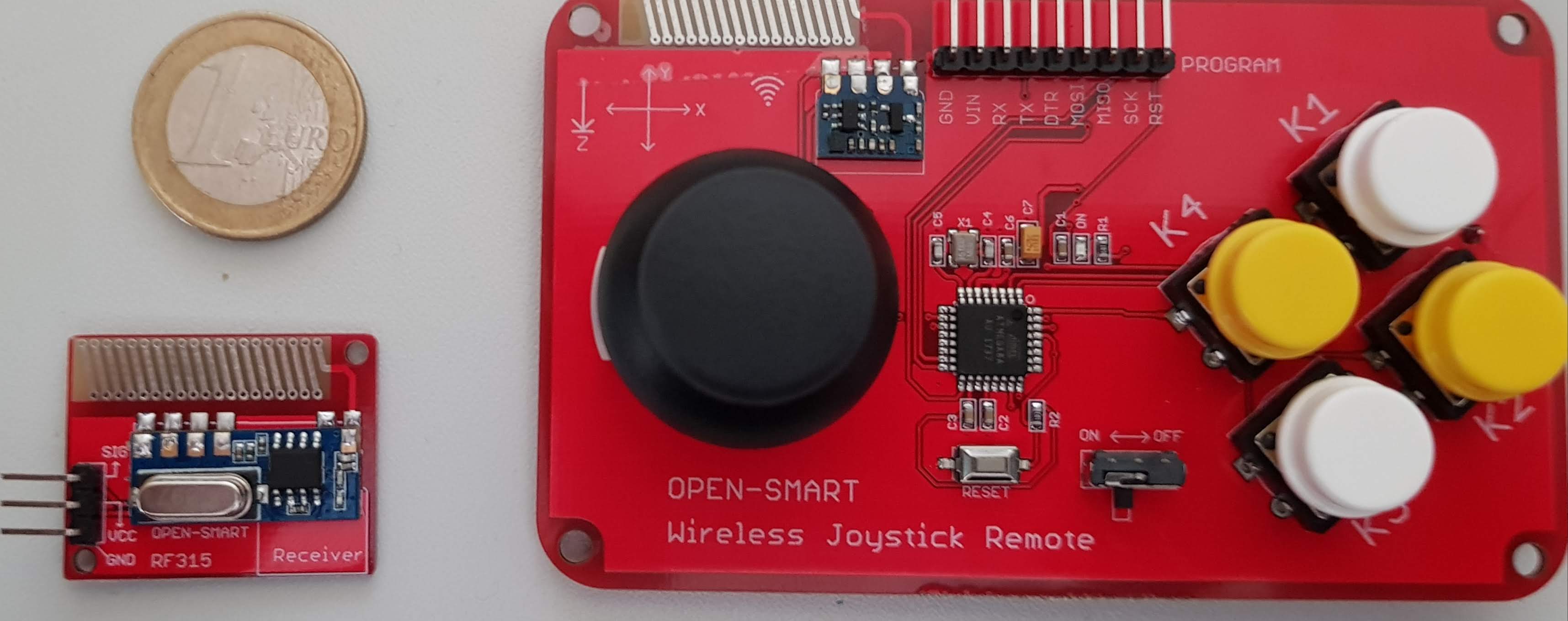
Ich brauchte eine Fernsteuerung und fand dieses interessante Board mit Empfänger für unter 5€. Mal schauen was es so kann.
Facts
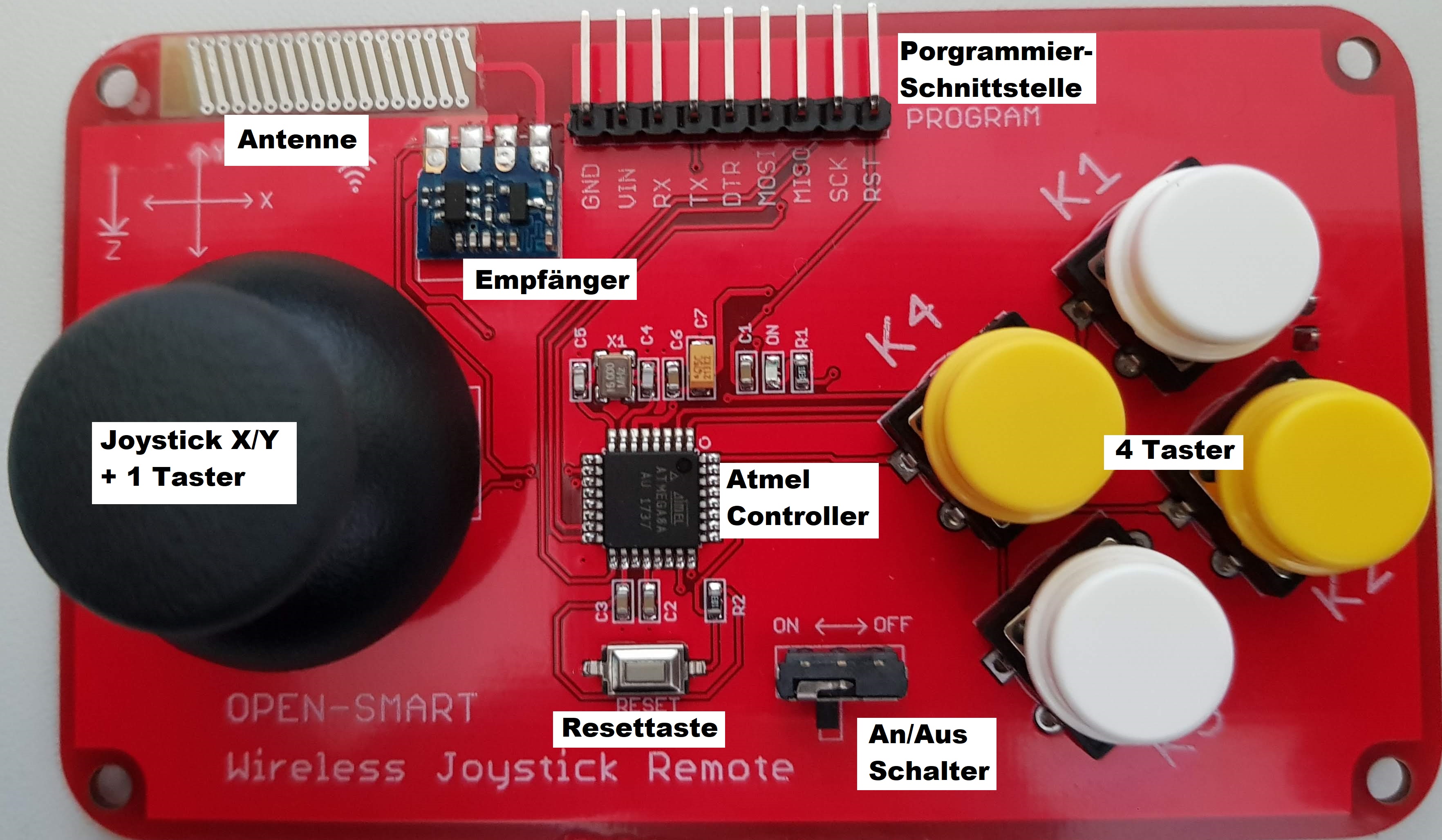
Joystick board
| Description | Worth |
| Operating voltage | 3V – 5.3V |
| Workflow | 42mA (max) |
| Controller | ATmega8A |
| Onboard sender | RF 315 / 433 MHz |
| Transfer rate | 2000 bps |
| Range at 5V | up to 150m |
| Battery socket | 2.54mm pitch |
Receiver module
RF 315 / 433 MHz (Likely RFM83C)
| Description | Worth |
| Operating voltage | 3V – 5.3V |
| Work current | 2 milliamp |
| Operating frequency | 433 MHz |
| Sensitivity | -110 dB |
| Transfer rate | 2000 bps |
| Control | VirtualWire Library |
Areas of application
- Remote-controlled toy
- Control unit
Views
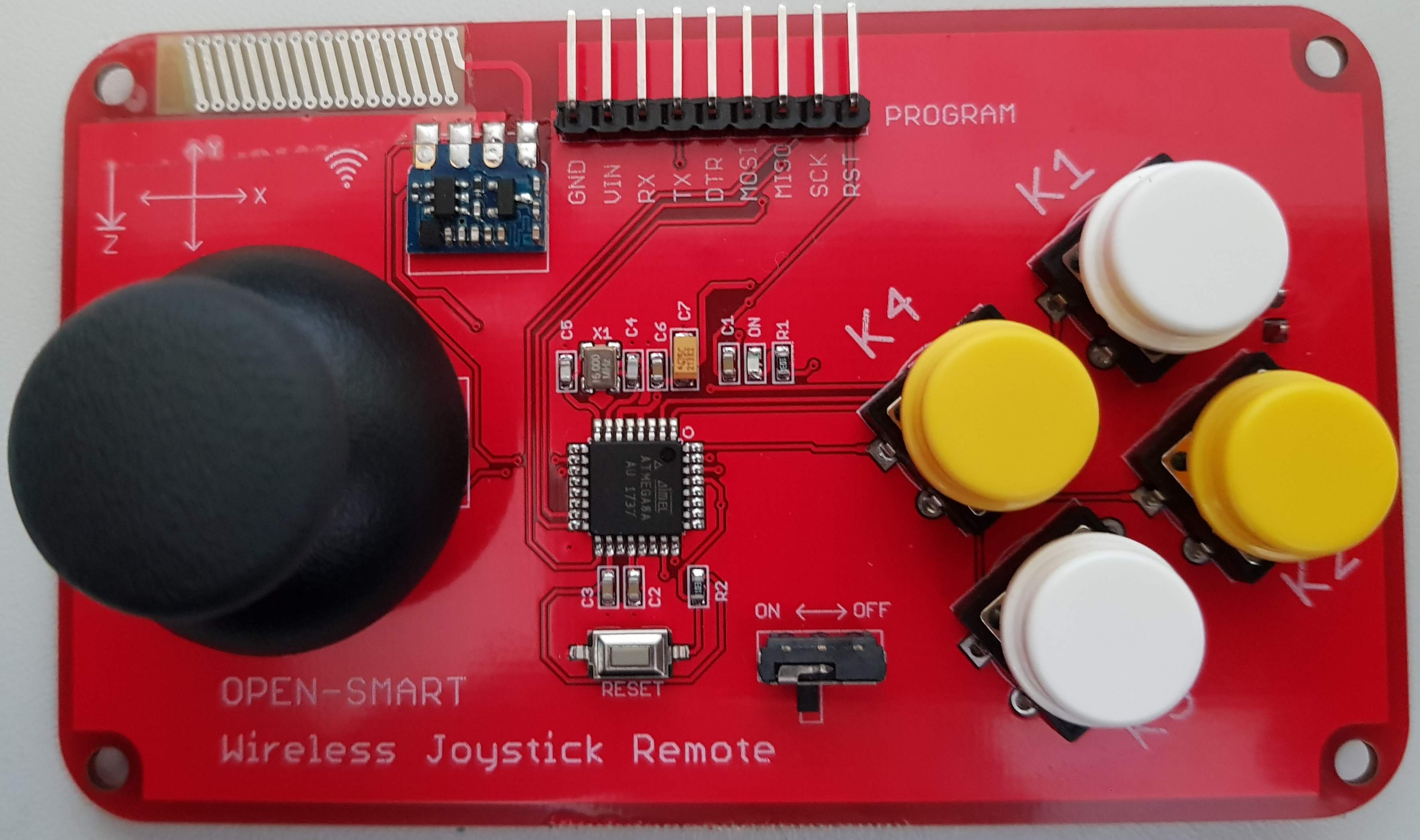
OPEN-SMART Remote Control Front 
OPEN-SMART Fernbedienung Rückseite 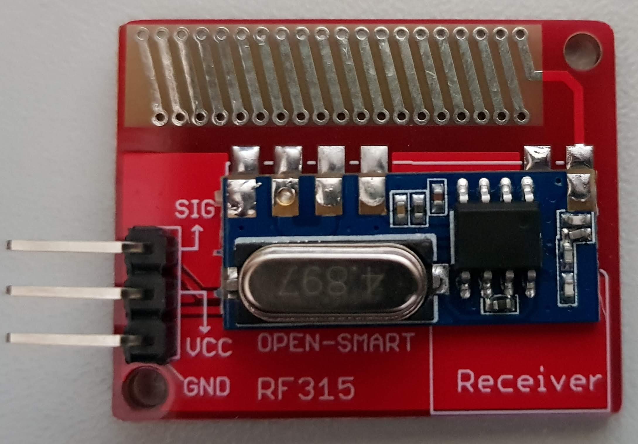
OPEN-SMART Fernbedienung Empänger Vorderseite 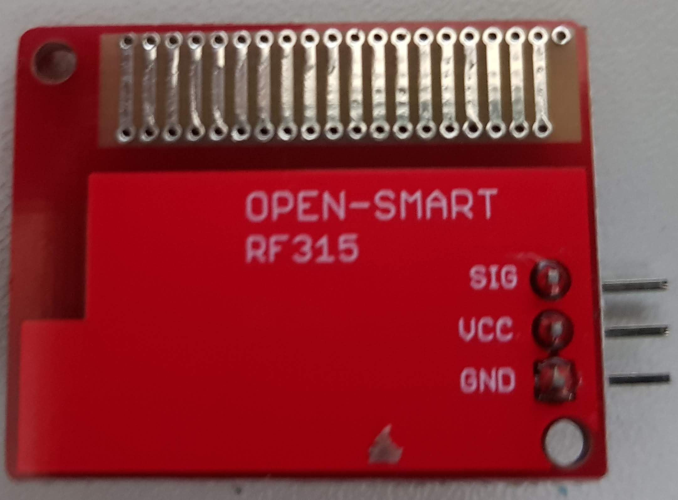
OPEN-SMART Fernbedienung Empänger Rückseite
Programming
Libraries
https://www.airspayce.com/mikem/arduino/VirtualWire/
Remote control test
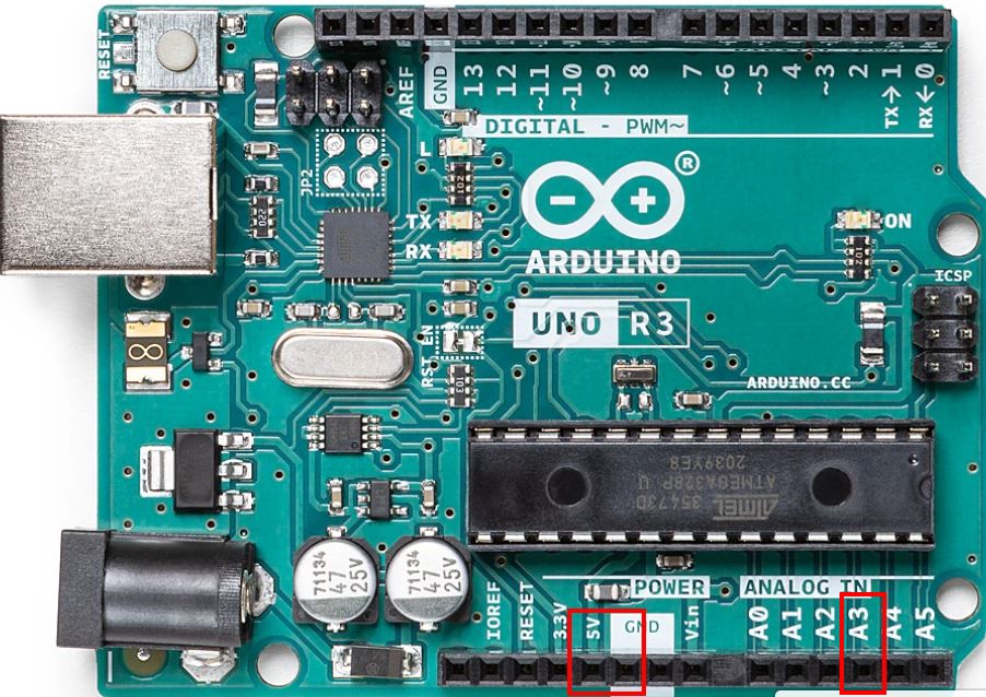
There is a vehicle from OPEN-SMART and the corresponding Program files dafür. Die Codestellen für den Empfänger habe ich ihnen entnommen und die Fernsteuerung unangetastet gelassen. Der Code geht davon aus, dass der Emfpänger am Port A3 angeschlossen ist und über den Arduino mit Strom versorgt wird.
‚); document.write(‚
‚);
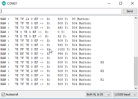
21.11.2021 Test program code modified again
Output will now be generated during initialisation to show what is currently pending. Additionally, a note will be written to the console every 2 seconds if no message has been received.
Problems
RF Verbindung unzuverlässig
Am Anfang hatte ich das Problem, dass die Verbindung nicht besonders zuverlässig war. Knopfdrücke wurden nicht übermittelt und die Werte des Joysticks waren sehr digital.
Finger on the aerial
Das Hauptproblem ist, die Fernbedienung is so gebaut, dass man automatisch auf die Antenne greift wenn man sie anfasst. Die Antenne habe ich mit Tesa abgeklebt, brachte aber nicht viel. Das Beste ist die Berührungen zu vermeiden. Evtl. könnte man hier überlegen eine Externe Antenne anzubringen.
More power
Ich hatte die Fernsteuerung vorher mit 3,7V betrieben (LIPO). Testweise habe ich sie mal über einen Arduino mit 5V versorgt. Die Übertragen scheint danach besser zu sein.
Play in
Es scheint so als müssten Sender und Empfänger sich immer erst etwas einpegeln. So ist nach dem Start die Verbindung schlecht wird aber immer besser. (Hier bin ich mir nicht mehr so sicher, seitdem ich die Finger von der Antenne lasse scheint das kein Problem mehr zu sein)
Conclusion
Eine sehr günstige Fernbedienung mit allem was man braucht. Ein zusätzlicher Vorteilen ist, dass man nur einen Pin benötigt um den Empfänger zu betreiben.
Die Antenne ist nicht sonderlich gut angebracht, auch wäre hier eine externe sicherlich besser. Ein Spannungregler, um die Fernbedienung auch mit 7,2 Volt betreiben zu können wäre Praktisch, da 5 Volt LIPOs nicht die Regel sind. Mit 4 AA Akkus komme ich jedoch auch so hin.
Den Schaltplan und ein Testprogramm musste ich beim Händler anfordern, das steht noch aus, evtl. gibt es hier noch neue Informationen.
Verwandte Beiträge
- Pan Tilt with joystick
- RC car with PS2 controller
- Funduino JOYSTICK V1.A
- Sunfounder nRF24 Remote Control
- Arduino PS2 Controller Board Fundamentals
Sources
https://www.instructables.com/id/RF-315433-MHz-Transmitter-receiver-Module-and-Ardu/
http://stefanfrings.de/avr_tools/
https://www.airspayce.com/mikem/arduino/VirtualWire/
https://drive.google.com/drive/folders/165f_72hYv0BfzqsM-8aNZV_CUyNK8v6m
https://drive.google.com/drive/folders/1erXeRAHAdsv7dMubP0oy1Bkq4knRVDn3
| Date | Change | Author |
|---|---|---|
| 29.06.2019 | Post created | Suffocation |
Hello,
I'm not quite clear on your setup yet, do you have a link to the China car? Is it the same FB?
Hello
Stefan
https://de.aliexpress.com/item/32864937005.html?spm=a2g0s.9042311.0.0.27424c4dS5Afaf
I have connected the receiver to my Uno and wanted to transmit a signal with the remote control.
Hi Siegfried, ok that's the same part.
I've unpacked the code and my hardware and tested them again. I've now also uploaded the code with the VirtualWire lib to GitHub:
https://github.com/sfambach/arduino/blob/master/projects/OpenSmartWirelessJoystickTest/
Otherwise, I'd only know trivial stories like:
Cables swapped
Analogue ports start with A0, making A3 the 4th analogue port.
You mustn't touch the aerial on the transmitter, otherwise it won't work (top and bottom). Electrical tape won't help 🙂
Sender powered on, green LED lit.
I am supplying my transmitter with a 3.7V LiPo via the GND/VIN programming pins.
You've surely checked all of that already, otherwise, I unfortunately can't think of anything else.
I had to approve your post from this morning because it contained a link. It's for my own protection, otherwise I get spammed by Russian porn sites ;). I've deleted the second one, I hope that was okay.
Hello
Stefan
Hello Stefan, ok I'll use the code again tomorrow. The cable (it's only a signal cable) is definitely connected to the Arduino. The LED on the joystick is also on. The 3.7v battery is also connected correctly.
My receiver has no display, but I have an oscilloscope and can't detect any reaction on the data line, at least when actuating the joystick.
The Chinese seller also has no idea, which is why I ordered a new joystick.
Siegfried
Hello Stefan, I tried your test on my remote control today, but I'm not getting any reaction on the monitor. I suspect the transmitter isn't working or the chip is faulty.
I bought a car from a Chinese seller with a joystick remote control, and unfortunately, I can't use the remote.
Are there any other testing options?
Yours sincerely